


Greensmaster 3320/3420 Page 6 -- 37 Electrical System
Electrical System Quick Checks
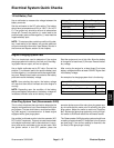
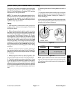
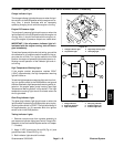
12 Volt Battery Test
Use a multimeter to measure the voltage between the
battery terminals.
Set the multimeter to the DC volts setting. The battery
should be at a temperature of 60
o
to 100
o
F(16
o
to 37
o
C). The ignition key should be off and all accessories
turned off. Connect the positive (+) meter lead to the
positive battery post and the negative (--) meter lead the
negative battery post.
NOTE: This testprovides a relative condition ofthe bat-
tery. Load testing of the battery will provide additional
and more accurate information (see Battery Service in
the Service and Repairs section of this chapter).
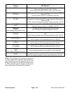
Voltage Measured
Battery Charge Level
12.68 VDC (or higher) Fully charged (100%)
12.45 VDC 75% charged
12.24 VDC 50% charged
12.06 VDC 25% charged
11.89 VDC 0% charged
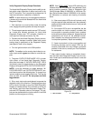
Engine Charging System Test
Thisisasimpletestusedtodetermineiftheengine
chargingsystem isfunctioning.Itwill tell you if the charg-
ing system has an output, but not its capacity.
Use a digital multimeter set to DC volts. Connect the
positive (+) multimeter lead to the positive battery post
and the negative(--) multimeterlead to the negative bat-
tery post. Keep the test leads connected to the battery
posts and record the battery voltage.
NOTE: Upon starting the engine, the battery voltage
will drop and then should increase once the engine is
running.
NOTE: Depending upon the condition of the battery
charge and battery temperature, the battery voltage will
increase at different rates as the battery charges.
Start the engine and run at high idle. Allow t he battery
to charge for at least three (3) minutes. Record the bat-
tery voltage.
After running the engine for at least three (3) minutes,
battery voltage should be at least 0.50VDC higher than
initial battery voltage.
An example of a charging system that is functioning:
At least 0.50 volt over initial battery voltage.
Initial Battery Voltage = 12.30V
Battery Voltage after 3 Minute Charge = 12.95V
Difference =+0.65V
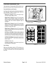
Glow Plug System Test (Greensmaster 3420)
This is a fast, simple test that can help to determine the
integrity and operation of your Greensmaster 3420 glow
plug system. The test should be run a nytime hard start-
ing (cold engine) is encountered on a diesel engine
equipped with a glow plug system.
Use a digital multimeter and/or inductive ammeter (AC/
DC Current Transducer). Properly connect the ammeter
to the digital multimeter (refer to manufacturers’ instruc-
tions) and set the multimeter to the correct scale. With
the ignition switch in the OFF position, place the
ammeter pickup around the main glow plug power sup-
ply wire and read the meter prior to activating the glow
plug system. Adjust the meter to read zero (if applica-
ble). Activate the glow plug system by turning the igni-
tion switch to RUN and record the multimeter results.
The Greensmaster 3420 glow plug system should have
a readingof approximately 27 amps total(nine (9) amps
per glow plug). If low current reading is observed, one
(or more) of the glow plugs is faulty.
Electrical
System