


Greensmaster 3320/3420 Hydraulic SystemPage 5 -- 65
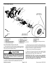
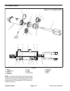
6. Make sure that lock nut on wheel motor shaft is loos-
ened at least two (2) turns. Use hub puller (see Special
Tools) to loosen brake drum assembly from wheel mo-
tor.
7. Remove lock nut and brake drum assembly. Locate
and retrieve woodruff key (item 12).
8. Remove four (4) cap screws that secure brake as-
sembly to wheel motor. Remove brake assembly. If
brake service is required, see Brake Service in the Ser-
vice and Repairs section of Chapter 7 -- Chassis.
9. Thoroughly clean hydraulic line ends and fittings on
wheelmotor toprevent hydraulicsystem contamination.
10.Label hydraulic connections at wheel motor for as-
sembly purposes.
11.Disconnect hydraulic linesfrom fittings onwheel mo-
tor. Allow lines to drain into a suitable container.
12.Mark wheel motor fitting orientation to allow correct
assembly. Remove hydraulic fittings and O--rings from
motor. Discard removed O--rings.
13.Put clean caps or plugs on disconnected lines and
motor port openings to prevent contamination.
14.Support wheel motor to prevent it from falling. Re-
move four (4) cap screws that secure wheel motor and
brake lever tab (item 10) to frame. Remove brake lever
tab and wheel motor from machine.
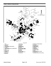
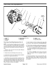
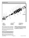
Front Wheel Motor Installation (Fig. 45)
1. Position hydraulic wheel motor tothe frame with mo-
tor ports facing up. Place brake lever tab (item 10) to
wheel motor with slot toward rear of machine. Secure
motor and brake lever tab to the frame with four (4) cap
screws.
2. Remove plugs from wheel motor ports. Lubricate
and place new O--rings onto fittings. Install fittings into
motor openings making sure that fitting orientation is as
notedduring removal. Tighten fittings(see HydraulicFit-
tingInstallationin theGeneralInformation section ofthis
chapter).
3. Remove caps from disconnected hydraulic lines.
4. Lubricate and position new O--rings to fittings on
wheel motor. Use labels placed during the removal pro-
cess to properly install hydraulic lines to wheel motor fit-
tings (see Hydraulic Hose and Tube Installation in the
General Information section of this chapter).
5. Position brake assembly to wheel motor and align
brake actuator lever with slot in brake lever tab. Secure
brakeassembly towheelmotor withfour (4)cap screws.
6. Thoroughly clean wheel motor shaft and wheel hub
taper.
7. Install woodruff key into the wheel motor shaft key-
slot. Align brake drum assembly with woodruff key and
slide drum assembly onto motor shaft. Secure drum as-
sembly with lock nut.
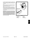
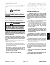
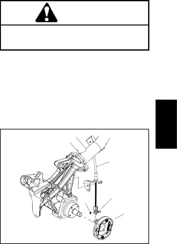
8. Secure brake cable clevis to brake actuator lever
with clevis pin and e--ring (Fig. 46).
9. Install front wheel to machine and secure with four
(4) lug nuts.
Failure t o maintain proper wheel lug nut and
wheel hub lock nut torque could result in failure
or loss of wheeland may result in personal injury.
WARNING
10.Lower machine to ground. Torque lock nut from 250
to 400 ft--lb (339 to 540 N--m) and wheel lug nuts from
65 to 85 ft--lb (89 to 115 N--m).
11.Check oil level in hydraulic reservoir and add correct
oil if necessary.
12.Follow Hydraulic System Start--up procedures (see
Hydraulic System Start--up in this section).
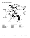
1. Brake cable
2. Clevis pin
3. E--ring
4. Brake assembly
Figure 46
1
2
4
3
Hydraulic
System