


Greensmaster 3420 Page 4 -- 19 Diesel Engine
CAUTION
When installing engine assembly, make sure lift
or hoist can safely support 190 lbs (86 kg).
5. Attach a suitable lift or hoist to engine.
IMPORTANT: Make sure to not damage the engine,
fuel hoses, hydraulic lines, electrical harness or
other parts while installing the engine.
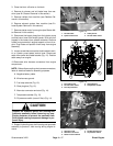
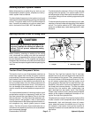
6. Slowly move the engine assembly toward the bell
housing to allow the pump coupling to slide into the en-
gine coupling flange (Fig. 17). Route generator belt to
pulley as engine is being moved into place.
7. Secure engine to machine:
A. Secure engine support (item 23) to enginemount
with removed fasteners (Fig. 15).
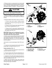
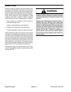
B. Secure bell housing to flywheel plate with five (5)
flange head screws (Fig. 16).
C. Secure rear engine plate and bell housing to rear
engine mount with two (2) cap screws, washers and
lock nuts (Fig. 16).
8. Connect throttle cable to the swivel on injector pump
speed control lever (Fig. 12). Adjust throttle cable and
secure to bracket (see Adjust Throttle Cable in the Ad-
justments section of this chapter).
9. Install starter motor to engine (see Starter Motor
Installation in this section).
10.Install exhaustsystem tomachine(see ExhaustSys-
tem Installation in this section).
11.Install radiator (see Radiator Installation in this sec-
tion).
12.Install air cleaner to machine (see Air Cleaner Instal-
lationin this section). Makesure thatallhoseclamps are
properly tightened.
13.Connect all electrical harness connectors to engine
using labels placed during engine removal.
14.Insert fuel supply hose and fuel return hose through
grommets inengine support on front of engine.Remove
plugs placed during engine removal from hoses. Con-
nect fuelsupply hoseto the injector pump fittingand fuel
return hose to the #3 injector fitting. Secure fuel hoses
with hose clamps.
15.Position generator belt onto pulley and tension belt
(seeGeneratorBelt( Greensmaster 3420)in theService
and Repairs section of Chapter 6 -- Electrical System).
16.Open fuel shutoff valve on fuel tank. Check tank and
hoses for leaks.
17.Fill cooling system with coolant. Check radiator and
hoses for leaks.
18.Make sure that alternator belt tension is properly ad-
justed.
19.Make sure that engine oil level is correct.
20.Connect battery cables to battery. Connect positive
battery cable first and negative cable last.
21.Bleed fuel system.
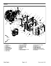
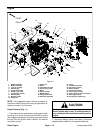
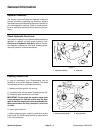
1. Piston pump
2. Cap screw (2 used)
3. Flat washer (2 used)
4. Coupling
5. Cap screw
6. Spacer
7. Engine coupling flange
8. Bell housing
9. Key
10. Generator drive pulley
Figure 17
1
9
6
5
7
8
27 to 33 ft--lb
(37 to 44 N--m)
Loctite #242
3
4
2
10
FRONT
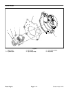
Figure 18
1. Engine
2. Coupling flange
3. Generator pulley
4. Flange screw (5 used)
3
4
2
1
FRONT
Diesel
Engine