


Rev. A
Greensmaster 3320/3420 Page 6 - 47 Electrical System
Electric Reel Drive System (48 Volt DC) Fuses
Several fuses are used in the electric reel drive system
for circuit protection. These fuses plug into fuse holders
and arelocated underthe sidecovernext totheoperator
seat.
Fuse Identification and Function
Use Figures 47, 48 and 49 (if equipped) to identify the
electric reel drive system fuses.
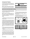
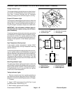
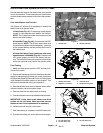
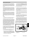
10 Amp Fuse (Fig. 47): Protects logic power supply
circuits for the generator and electric reel motors.
NOTE:The10 ampfuse holderisacomponentofthe
electric reel wire harness.
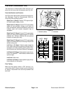
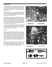
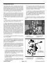
60 Amp Maxi Fuse (Fig.48): Protects main 48VDC
power supply. NOTE: The 60 amp fuse holder wire
connectionsare attached tothenegative(-) terminal
on the forward battery and the junction block next to
the battery pack.
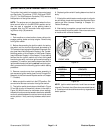
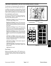
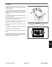
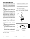
35 Amp Reel Motor Fuses (machines with serial
numberabove315000000)(Fig.49):Protectthe48
VDC power supply circuits for the electric reel mo-
tors. Thereel motorfuses arelocated ina fuseholder
under the right side cover next to the operator seat.
Fuse Testing
1. Make sure that ignition switch is OFF and key is re-
moved from switch.
2. Disconnect thecutting un itsfromtheelectricalpower
supply by separating the cutting unit power disconnect
couplers (see OpeningElectrical Circuit to Cutting Units
in the General Information section of this chapter). This
will prevent unexpected cutting unit operation.
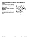
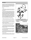
3. Remove leftside cover next to operator seat to allow
access to electric reel drive system fuses.
4. Remove fuse from the fuse holder for testing.
5. Fuseshould have continuity between fuse terminals.
IMPORTANT: Fuses used in the electric reel drive
system are 58 volt fuses. Make sure that correct
fuses are used if fuse replacement is necessary.
6. Install functional fuse into fuse h older.
7. After fuse testing is complete, install left side cover.
8. Connect the cutting unit power disconnect couplers.
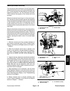
1. 10 amp fuse 2. 60 amp maxi fuse
Figure 47
1
2
1. 60 amp fuse holder
2. Negative (-) terminal
3. Junction block
4. Disconnect couplers
Figure 48
1
2
3
4
1. #1 reel motor fuse
2. #2 reel motor fuse
3. #3 reel motor fuse
Figure 49
1
2
3
Electrical
System