


Greensmaster 3320/3420 Page 6 -- 93 Electrical System
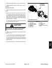
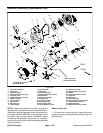
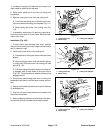
6. Remove cap screws (item 6), flat washers (item 7)
and flange nuts(item10) thatsecure controller to gener-
ator assembly. Lift controller from generator. Remove
and discard O--ring (item 24).
NOTE: If controller (item 9) damage exists, controller
replacement is necessary. Internal c ontroller compo-
nents are not available separately.
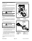
7. Removeflangehead screw (item16)and collar (item
15) from generator shaft.
8. Remove generator fan. Generator fan can be re-
moved with collar (item 15), three (3) fan screen screws
(item 18),a 3/8” -- 16 UNCcap screw anda thick washer
or spacer as follows:
IMPORTANT: To prevent damage to generator shaft
threads, position a thick washer or spacer on the
end of the shaft before removing the generator fan.
A. Position thick washer or spacer on the end of the
generator shaft.
B. Position collar (item 15) to generator fan and
alignthree (3)holes incollarwith tappedholesin fan.
C. Insert three (3) torx screws (item 18) through col-
lar a nd into threaded holes in fan.
D. Thread 3/8” -- 16 UNC cap screw into center hole
of collar and against washer on generator shaft.
E. Support fan to prevent it from falling and then
tighten screw to remove fan.
F. Locate and retrieve woodruff key (item 22).
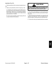
9. Remove retaining ring (item 5), wave washer (item
4) and flocked seal ( item 3) from generator shaft. Note
orientation of flocked seal for assembly purposes.
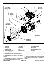
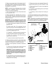
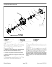
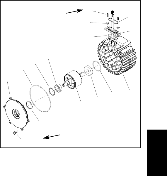
10.Remove internal generator assembly components
(Fig. 108):
A. Remove six (6) flange head screws that secure
cover to housing. Leave cover on rotor shaft.
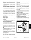
IMPORTANT: The rotor magnets are very power-
ful and can cause the rotor to shift position very
rapidly during removal. Be cautious during rotor
removal to prevent component damage or per-
sonal injury.
B. Use generator rotor tool set (see Special Tools in
this chapter) to carefully remove rotor assembly in-
cluding cover from housing.
C. Remove cover from rotor assembly. Remove O--
rings and wave washer fromcover. Discard O--rings.
D. RemoveanddiscardO--ring from housinggroove
in bearing bore.
E. Ifnecessary,remove bearings fromrotor.Discard
bearings if removed.
F. If necessary, remove isolator from housing as-
sembly.
11.Inspect rotor assembly forwearordamage.Also,in-
spect generator housing/stator assembly for evidence
of damage.
NOTE: Ifgenerator housing/statordamage exists,gen-
eratorassembly replacementis necessary.Thegenera-
tor housing and stator are not available separately.
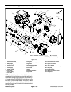
1. Housing/stator assembly
2. O--ring
3. Bearing
4. Rotor assembly
5. Bearing
6. Wave washer
7. O--ring
8. O--ring
9. Cover
10. Flange screw (6 used)
11. Screw (2 used)
12. O--ring
13. Spacer (2 used)
14. Isolator
15. Gasket
Figure 108
170 to 190 in--lb
(19.3 to 21.3 N--m)
2
3
6
8
9
10
1
5
7
4
11
12
13
14
15
35 to 45 in--lb
(4.0 to 5.0 N--m)
Electrical
System