


Greensmaster 3320/3420 Hydraulic SystemPage 5 -- 73
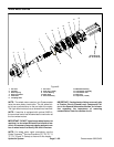
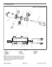
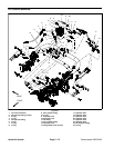
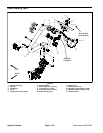
Disassembly (Fig. 50)
1. Remove the oil from the lift cylinder by slowly pump-
ing the cylinder shaft while holding the cylinder over a
drain pan. Plug both ports and clean the outside of the
cylinder.
IMPORTANT: Prevent damage when clamping the
lift cylinder in a vise; clamp on the rear mounting
flange only. Do not close vise on the barrel.
2. Mount lift cylinder in a vise. Use of a vise with soft
jaws is recommended.
3. Using a spanner wrench, rotate head clockwise until
the edge of the retaining ring (item2) appearsin thebar-
rel opening. Insert a screwdriver under the beveled
edge of the retaining ring to start the retaining ring
through the opening. Rotate the head counter--clock-
wise to remove retaining ring from barrel and head.
4. Extract shaft, head and piston assembly by carefully
twisting and pulling on the shaft.
IMPORTANT: Do not clamp vise jaws against the
shaft surface. Protect shaft surface before mount-
ing in a vise.
5. Mountshaftsecurelyin aviseby clampingon thecle-
vis of the shaft. Remove lock nut and piston from the
shaft. Slide head off the shaft.
6. Remove wear ring, piston seal and O--ring from the
piston. Remove O--ring, back--up ring, head seal and
dust seal from the head.
CAUTION
Use eyeprotection such asgoggles when using
compressed air to dry cylinder parts.
7. Wash lift cylinder parts in clean solvent. Dry parts
with compressed air. Do not wipe parts dry with paper
towels or cloth. Lint in a hydraulic system will cause
damage.
8. Carefully inspect internal surface of barrel for dam-
age (deep scratches, out--of--round, etc.). Inspect shaft,
head and piston for evidence of excessive scoring, pit-
ting or wear. Replace entire cylinder if internal compo-
nents are found to be worn or damaged.
Assembly (Fig. 50)
1. Make sure all lift cylinder parts are clean before as-
sembly.
2. Coat new seal kit components with clean hydraulic
oil.
A. Install wear ring, piston seal and O--ring on the
piston.
B. Install O--ring, back--up ring, head seal and dust
seal on the head.
IMPORTANT: Do not clamp vise jaws against the
shaft surface. Protect shaft surface before mount-
inginavise.
3. Mountshaftsecurelyina vise byclamping on the cle-
vis of the shaft. Use of a vise with soft jaws is recom-
mended.
A. Coat shaft with clean hydraulic oil.
B. Carefullyslideheadontotheshaft.
C. Install piston and lock nut onto the shaft. Torque
lock nut from 40 ft--lb (54 N--m).
D. Remove shaft from the vise.
IMPORTANT: Prevent damage when clamping the
hydraulic cylinder into a vise; clamp on the rear
mounting flange only. Do not close vise on the bar-
rel.
4. Mount barrel in a vise. Use of a vise with soft jaws is
recommended.
5. Coat all internal parts with a light coat of clean hy-
draulic oil. Slide piston, shaft and head assembly into
the barrel being careful to not damage the seals.
6. Secure head in barrel by installing retaining ring.
Align retaining ring hole in the head with the access slot
in the barrel. Insert the retaining ring hook into the hole
and rotatehead clockwise untilthe retainingring is com-
pletelypulled intothe barreland the ringends arecover-
ed.
Hydraulic
System