


Greensmaster 3320/3420 Page 6 - 67 Electrical System
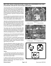
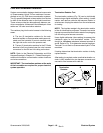
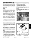
Starter Solenoid (Greensmaster 3320)
The starter solenoid used on Greensmaster 3320 ma-
chines allows current flow from the battery to the engine
starter motor when energized. This solenoid is ener-
gized by the TEC controller when the ignition switch is
in the START position. The starter solenoid is attached
to the left side ofthe rear frame beneaththe hydraulicoil
reservoir (Fig. 87).
Testing
NOTE: Before disconnecting and testing starter sole-
noid, test the TEC controller outputs with the Hand Held
Diagnostic Display (see Hand Held Diagnostic Display
in the Troubleshooting section of this chapter) or
InfoCenter Display (see InfoCenter Display in this
chapter). If the Diagnostic or InfoCenter Display verifies
that the TEC outputs are functioning correctly, consider
that a problem with the starter solenoid or circuit wiring
may exist. An open or shorted controller output (e.g. a
failedstarter solenoid, anunpluggedconnector or abro-
ken wire) cannot be detected with the Diagnostic or
InfoCenter Display. Conversely, if the Diagnostic or
InfoCenter Display verifies that the TEC outputs arenot
functioning correctly, consider that a problem with con-
troller inputs, controller fuses or the TEC controller may
exist.
1. Park machine on level surface, lower cutting units,
stop engine, apply parking brake and remove key from
ignition switch.
2. Disconnect negative (black) cable from battery and
then disconnect positive (red) cable (see Battery Ser-
vice in the Service and Repairs section of this chapter).
3. Note wire locations on starter solenoid for assembly
purposes. Disconnect cables and wire harness connec-
tors from solenoid.
NOTE: Prior to taking small resistance readings with a
digital multimeter, short the meter t est leads together.
The meter will display a small resistance value (usually
0.5 ohms or less). This resistance is due to the internal
resistance of the meter and test leads. Subtract this val-
ue from the measured value of the component you are
testing.
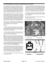
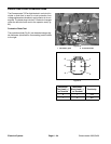
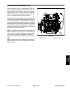
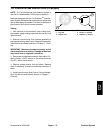
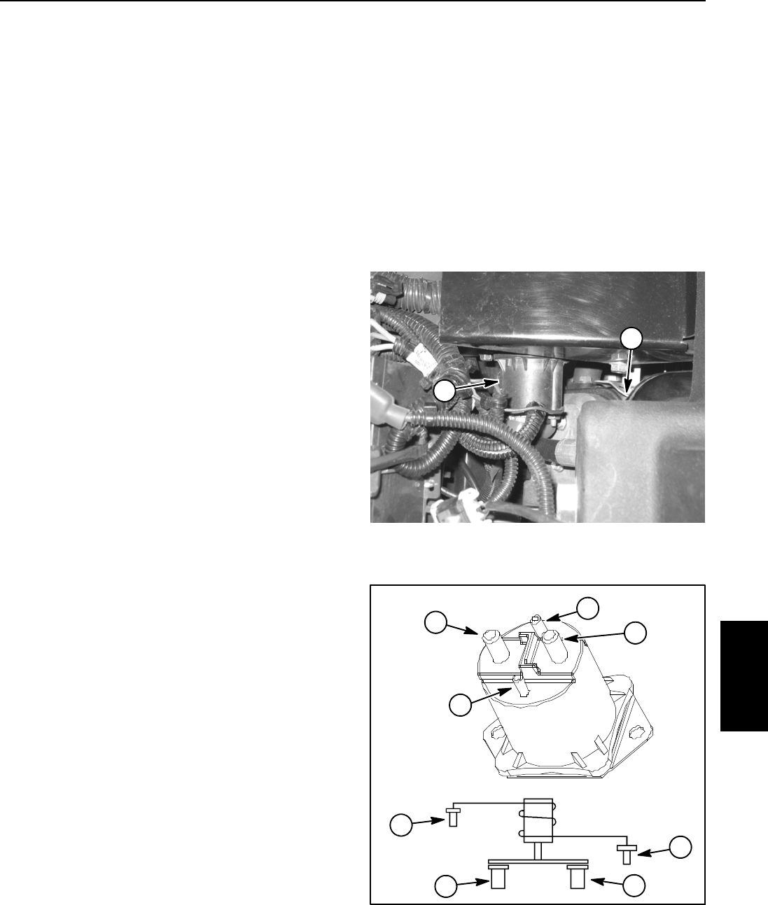
4. Apply 12 VDC directly across the solenoid coil posts
(steel). The solenoid should c lick as the solenoid coil is
energized. Make sure resistance across the main con-
tact posts (copper) is less than 1 ohm.
5. Removevoltage fromsolenoid coil posts (steel).The
solenoid should click as the solenoid coil is de- ener-
gized. Make sure resistance across the main contact
posts (copper) is infinite ohms.
6. Resistance across the solenoid coil posts (steel)
should be approximately 13.5 ohms.
7. Replace starter solenoid if necessary.
8. Connect positive battery cable to one main contact
post on starter solenoid, starter cable to the other main
contact post and two (2) wire harness connectors to so-
lenoid posts.
9. Connect battery cables to battery. Make sure to con-
nect positive (red) battery cable first and then connect
negative (black) cable.
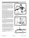
1. Hydraulic reservoir 2. Starter solenoid
Figure 87
2
1
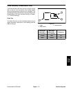
Figure 88
WIRING
DIAGRAM
1. Main posts (copper)
2. Solenoid posts (steel)
1
2
1
1
2
2
2
1
Electrical
System