


Greensmaster 3320/3420 Page 7 -- 13 Chassis
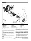
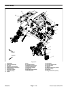
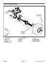
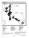
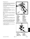
Disassembly (Fig. 11)
1. Parkmachine on alevel surface,engage theparking
brake, lower the cutting units and stop the engine. Re-
move key from the ignition switch.
2. Chockfront wheelsto preventmachine from shifting.
3. Remove rear wheel (see Wheel Removal in this sec-
tion). Make sure to support machine with jack stands.
4. Remove the dust cap from the wheel hub.
5. Remove the cotter pin, retainer, jam nut and tab
washer. Slide the wheel hub from the spindle shaft.
6. Pull the seal out of the wheel hub. Discard seal.
7. Remove the bearing cones from both sides of the
wheel hub. Cleanthe bearings insolvent. Make sure the
bearings are in good operating condition. Clean the in-
side of the wheel hub. Check t he bearing cups for wear,
pitting or other damage. Replace worn or damaged
parts.
8. If necessary, press wheel studs from wheel hub.
9. Inspect wheel spindle for wear or damage. If re-
quired, remove cap screws and flange nuts that secure
spindle to rear fork and remove spindle from machine.
Assembly (Fig. 11)
1. Ifwheel spindle wasremoved from rearfork, position
spindle to fork and secure with cap screws and flange
nuts.
2. If bearing cups were removed from the wheel hub,
press new cups into the hub until they seat against the
shoulder of the hub.
3. If wheel studs were removed from wheel hub, press
wheel studs into hub. Make sure thatstud shoulders are
fully pressed against hub surface.
4. Apply a light coating of grease to wheel spindle.
5. Pack both bearing cones with grease. Install one
bearingintothe bearingcup oninboard sideof thewheel
hub.
IMPORTANT: The lip of the seal must be toward the
bearing. The seal should be pressed in so it is flush
with the end of the wheel hub.
6. Lubricatetheinsideof anewsealand pressitinto the
wheel hub with the seal lip toward the bearing.
7. Fillwheel hub cavity between bearings approximate-
ly50% fullof grease. Positionremaining bearing intothe
outer bearing cup.
8. Carefully slide the wheel hub assembly onto the
spindle shaft and secure it in place with the tab washer
and jam nut. DO NOT fully tighten the nut or install the
cotter pin.
9. Whilerotating the wheel hub by hand, torque thejam
nutfrom75to100in-lb(8.5to11.3N--m)tosetthebear-
ings. Then, loosen the nut until the hub has endplay.
10.Again, while rotating the wheel hub by hand, torque
the jam nut from 15 to 20 in-lb (1.7 to 2.3 N --m).After
tightening, make sure that the wheel hub does not have
any free play.
11.Install retainer with slot aligned to cotter pin hole in
spindle. Install cotter pin.
12.Fill dust cap approximately half full of grease. Install
dust cap.
13.Install rear wheel (see Wheel Installation in this sec-
tion).
14.Lower machine to ground.
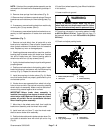
Failure to maintain proper wheel lug nut torque
could resultin failure orloss ofwheel and mayre-
sult in personal injury.
WARNING
15.Torque lug nuts evenly in a crossing pattern from 65
to 85 ft--lb (89 to 115 N--m).
Chassis