


Greensmaster 3320/3420 GroomerPage 9 -- 25
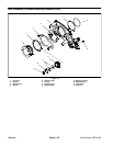
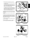
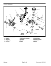
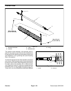
Disassembly (Fig. 31)
1. Park machine on a clean, level surface. Lower cut-
tingunits completely tothe ground, stop engine, engage
parking brake and remove key from the ignition switch.
2. Disconnect thecutting unitsfromtheelectrical power
supply by separating the cutting unit power disconnect
couplers (see Opening Electrical Circuit to Cutting Units
in the General Information section of this chapter). This
will prevent unexpected cutting unit operation.
3. Remove flange nut (item 2) that secures lift arm as-
semblyto HOCgroomerarm. Remove locknut (item16)
and spring washer (item 17) that secure lift arm as-
sembly to side plate. Loosen lock screw (item 6) com-
pletely.
4. Remove lift arm assembly from cutting unit.
5. Disassemble lift arm using Figure 31 as a guide.
NOTE: Right and left side HOC groomer arms (item 1)
and liftarm assemblies (item8) are different; other com-
ponents shown in Figure 31 are the same on both sides
of cutting unit.
NOTE: Groovedpin(item 3)isused toretainlock screw
(item 6) to lift arm assembly.
Assembly (Fig. 31)
1. Assemble lift arm using Figure 31 as a guide.
2. Apply antiseize lubricant to threads of groomer lift
rod (item 5) and lift arm assembly stud (item 8).
3. Installlift arm assemblyontocutting unit.Secure with
flange nut (item 2) and lock nut (item 16) with spring
washer (item 17).
4. Secure groomer in raised or lowered position with
lock screw (item 6).
5. Check and adjust grooming reel height and mower
height--of--cut settings.
6. Connect the cutting unit power disconnect couplers.
Groomer