


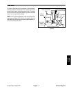
Greensmaster 3320/3420 Page 6 -- 11 Electrical System
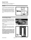
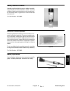
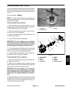
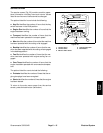
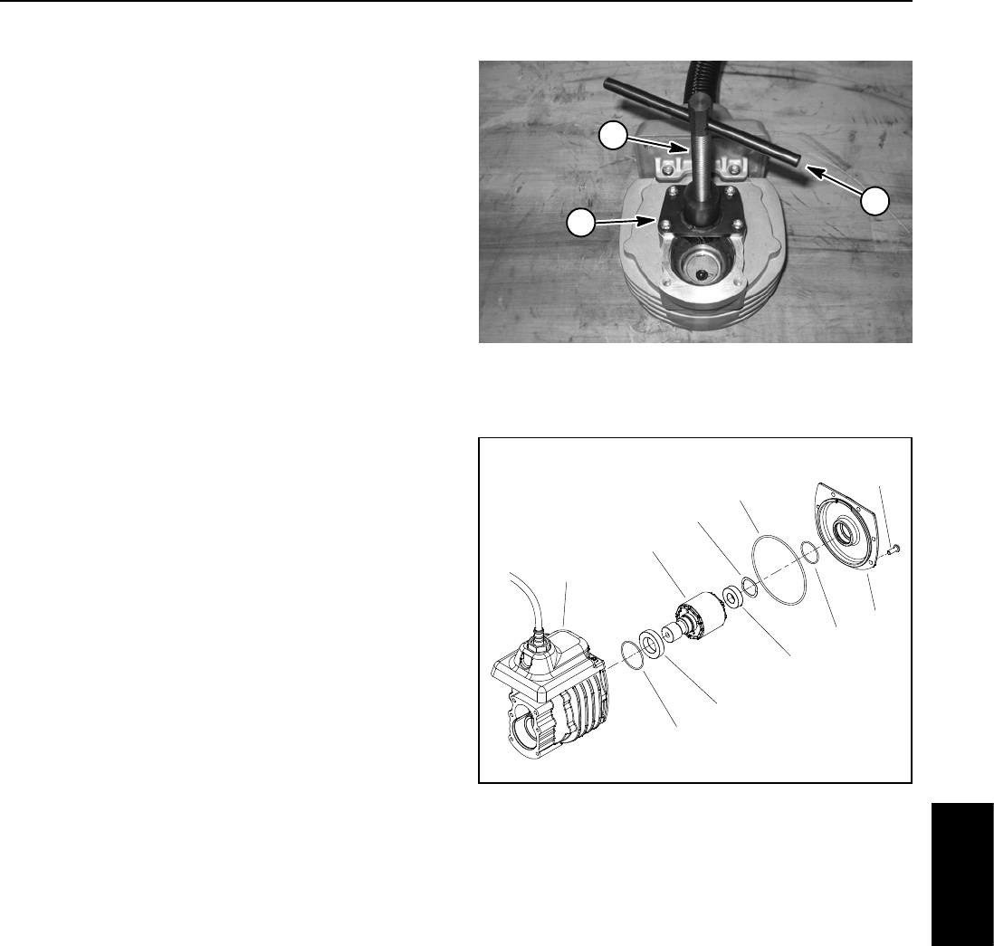
Cutting Reel Motor Rotor Tool Set
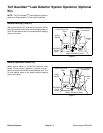
The rotor tool set for the cutting reel motor is required to
remove and installthe rotorfrom the reel motorhousing.
Tool set includes base plate, threaded shaft and handle
(Fig. 14).
Toro Part Number: TOR6028
NOTE: For cutting reel motor service procedures, see
Cutting Reel Motor Service in the Service and Repairs
section of this chapter.
Cutting Reel Motor Rotor Removal
1. Remove gearbox cover and output gear from motor
assembly (see Cutting Reel Motor Service in the Ser-
vice and Repairs section of this chapter).
2. Remove screws that secure motor cover. Do not re-
move cover from motor assembly.
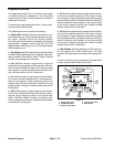
3. Secure tool set base plateto motor housing with four
(4) of the cover screws.
4. Install threaded shaft into base plate.
IMPORTANT: The rotor magnets are very powerful
and cancausethe rotorto shift positionveryrapidly
during removal.Be cautiousduringroto r removal to
prevent component damage or personal injury.
5. Turn threaded shaft with handle to remove rotor and
motor cover from motor housing. Support rotor to pre-
vent it from falling from housing during removal.
6. Leave threaded shaft installed in same position in
base plate for rotor installation purposes.
Cutting Reel Motor Rotor Installation
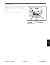
1. Secure tool set base plateto motor housing with four
(4) of the cover screws.
2. Make sure that threaded shaft is installed into base
plate so that the end of the threaded shaft prevents the
rotor body from entering the motor housing.
IMPORTANT: The rotor magnets are very powerful
and cancausethe rotorto shift positionveryrapidly
during installation. Be cautious during rotor instal-
lation topreventcomponent damage orpersonalin-
jury.
3. While guiding rotor into motor housing, slowly rotate
threadedshafttoallowtherotortobedrawnintothe
housing. Once rotor is fully installed into housing, re-
move tool set from motor housing.
Figure 14
1. Base plate
2. Threaded shaft
3. Handle
1
2
3
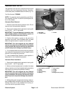
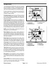
1. Screw (6 used)
2. Motor cover
3. O--ring
4. O--ring
5. Wave washer
6. Bearing
7. Rotor
8. Bearing
9. O--ring
10. Housing assembly
Figure 15
7
5
6
8
3
9
2
4
1
10
Electrical
System