


Greensmaster 3320/3420 Hydraulic SystemPage 5 -- 37
The steering/lift relief valve pressure test should be per-
formed to make sure that the relief pressure for the
steering and lift circuits is correct.
Procedure for Steering/Lift Relief Valve Pressure
Test:
1. Make sure hydraulic oil is at normal operating tem-
peraturebyoperatingthe machinefor approximatelyten
(10) minutes.
2. Parkmachineon alevelsurface withthe cuttingunits
lowered. Make sure engine is off and the parking brake
is engaged. Make sure the hydraulic tank is full.
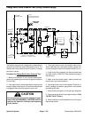
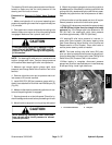
CAUTION
Prevent personal injury and/or damage to equip-
ment. Read all WARNINGS, CAUTIONS and Pre-
cautions for Hydraulic Testing at the beginning
of this section.
NOTE: The steering/lift relief valve is in series with the
traction charge relief valve. Traction charge pressure
will therefore affect steering/lift relief valve pressure.
3. Measure and record traction charge relief valve
pressure (see Charge Relief Valve Pressure Test in this
section).
4. Remove right side cover next to operator seat to al-
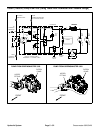
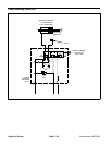
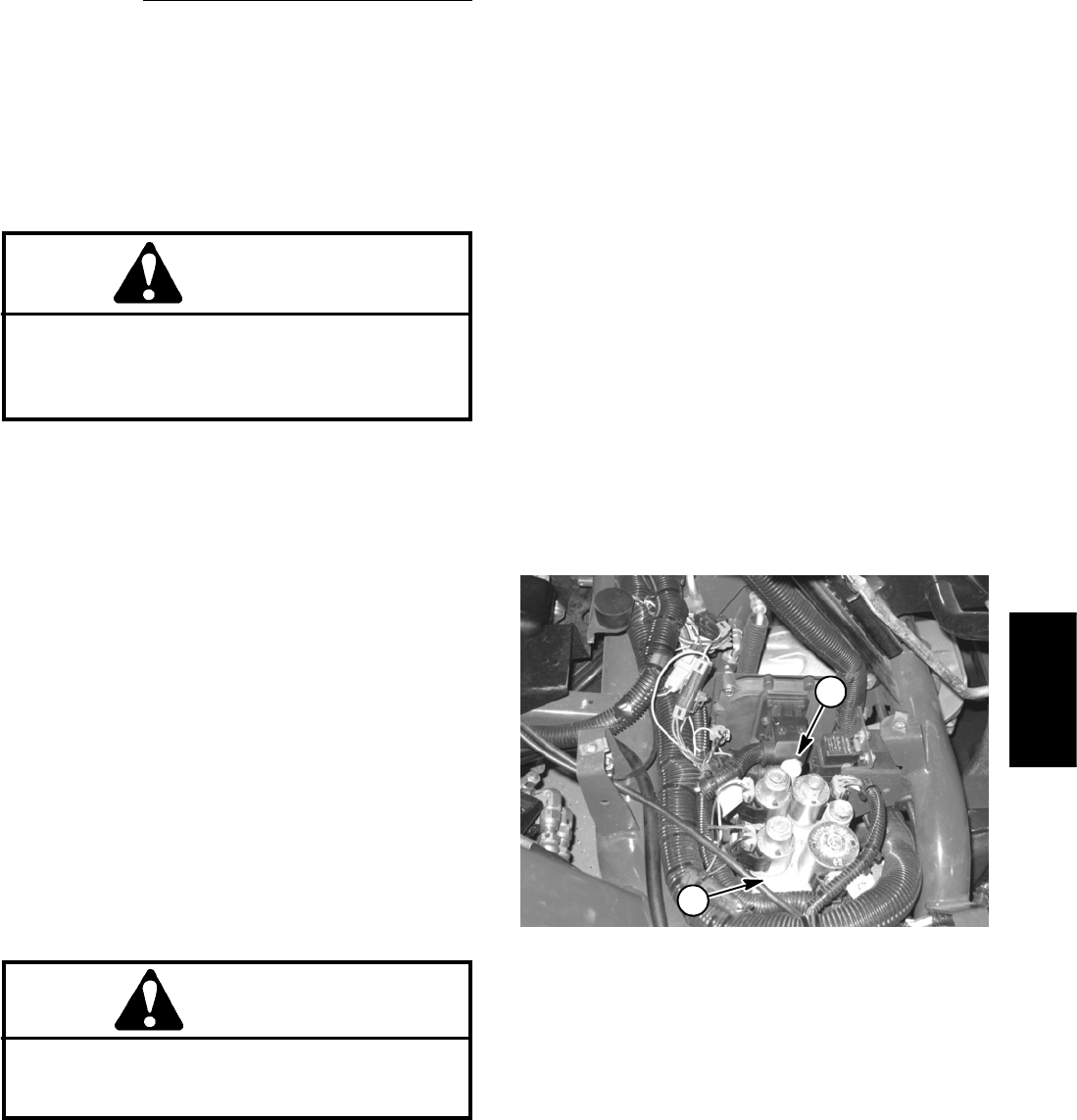
low access to lift control manifold.
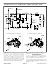
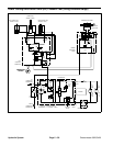
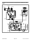
5. Install 5000 PSI (350 bar) pressure gauge with hy-
draulic hoseattached to lift control manifoldtest port (G)
(Fig. 22).
6. Makesure thattraction pedaland joystickare inneu-
tral and t he parking brake is engaged.
7. Start engine and run at low idle speed. Check for hy-
draulic leakage and correct before proceeding with test.
8. Move throttle soengine isrunning at high idle speed.
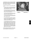
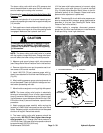
CAUTION
While measuring steering/lift relief valve pres-
sure, do not allow circuit pressure to exceed
1400 PSI (82.8 bar).
9. Watch the pressure gauge and move the joystick to
the raiseposition. Momentarilyhold thejoystick withthe
cutting units fully raised causing the relief valve to open.
Release the joystick when the relief pressure is identi-
fied.
10.Move throttle to low idle speed and shut off e ngine.
Record pressure at which the relief valve opens.
11.Steering/lift valve pressure should be approximately
1160 PSI (80 bar) higher than the charge relief valve
pressure (e.g.ifthechargerelief valve pressure is 125
PSI(8.6bar),thesteering/lift relief valve pressure
should be approximately 1285 PSI (88.6 bar)).
12.If steering/lift relief valve pressure is incorrect, in-
spect relief valve located in the power steering valve
(see Power Steering Valve Service in the Service and
Repairs section of this Chapter). Clean relief valve or
service power steering valve as needed.
NOTE: The lower cutting units relief valve (RV) pres-
sure can also be measured with pressure gauge posi -
tioned as described in this test (see Lower Cutting Units
Relief Valve (RV) Pressure Test in this section).
13.When testing is complete, disconnect pressure
gauge from lift control manifold test port. Install dust cap
to test port fitting. Install right side cover.
1. Lift control manifold 2. Test port
Figure 22
2
1
Hydraulic
System