


Greensmaster 3320/3420Page 6 -- 62Electrical System
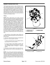
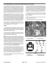
Kill (Greensmaster 3320) and Start (Greensmaster 3420) Relays
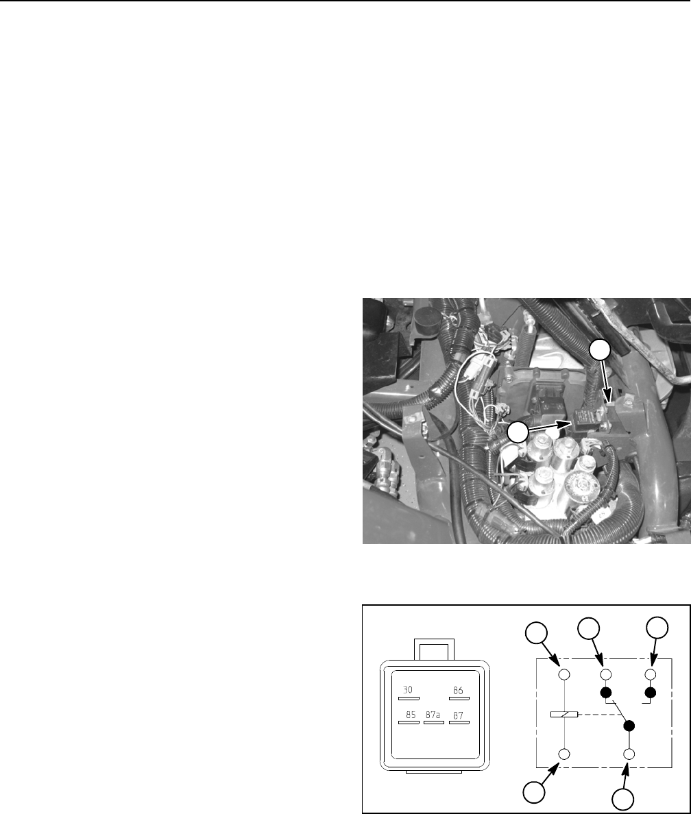
The Greensmaster TriFlex Hybrid electrical system in-
cludesafive (5)terminalrelayfor currentcontrol. The kill
relay is used only on Greensmaster 3320 machines.
The start relay is used only on Greensmaster 3420 ma-
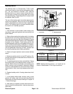
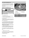
chines. These relays are located under the right side
covernextto theoperatorseat(Fig.77) andcan beiden-
tified by a tag near the relay wire harness connector.
When energized by the TEC controller, the kill relay on
Greensmaster 3320 machines provides a grounding
path for the engine starter solenoid. While energized,
the kill relay also allows the engine magneto (ignition)
system to function. When the kill relay is de--energized,
a grounding path is madefor the engine magneto arma-
tures to prevent ignition function and stop the engine.
The start relay on Greensmaster 3420 machines pro-
vides electrical current to the engine starter solenoid
when energized by the TEC controller.
Testing
1. Park machine on a level surface, lower cutting units,
stop engine, apply parking brake and remove key from
ignitionswitch. Remove rightside covernext tooperator
seat to allow access to relays.
2. Locate relay to be tested and disconnect the ma-
chine wire harness connector from t he relay. Remove
relay from bracket for easier testing.
NOTE: Prior to taking small resistance readings with a
digital multimeter, short the meter test leads together.
The meter will display a small resistance value (usually
0.5 ohms or less). This resistance is due to the internal
resistance of the meter and test leads. Subtract this val-
ue from the measured value of the relay being testing.
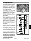
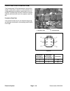
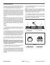
3. Using a multimeter (ohms setting), measure coil re-
sistance between terminals 85 and 86 (Fig. 78). Resist-
ance should be between 70 and 90 ohms.
4. Connectmultimeter (ohmssetting) leads torelay ter-
minals 30 and 87. Ground terminal 86 and apply +12
VDC to terminal 85. The relay terminals 30 and 87
shouldhave continuityas +12 VDCis applied to terminal
85. Therelay terminals 30and 87 should not haveconti-
nuity as +12 VDC is removed from terminal 85.
5. Disconnect voltage from terminal 85 and multimeter
lead from terminal 87.
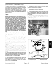
6. Connectmultimeter (ohmssetting) leads to relayter-
minals 30 and 87A. With terminal 86 grounded, apply
+12 VDCto terminal 85. The relay terminals 30 and 87A
should not have continuity as +12 VDC is applied to ter-
minal 85. The relay terminals 30 and 87A should have
continuity as +12 VDC is removed from terminal 85.
7. When relay testing is completed, disconnect voltage
and multimeter leads from the relay terminals. Replace
relay if necessary.
8. Secure relay to machine and connect machine wire
harness connector to relay.
9. Install right side cover next to operator seat.
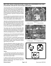
1. Relay (4 terminal) 2. Relay (5 terminal)
Figure 77
2
1
Figure 78
86
85
87A 87
30
2
1
3
4
1. Coil terminal
2. Common terminal
3. Normally closed term.
4. Normally open term.
1