


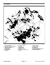
Greensmaster 3320/3420 Hydraulic SystemPage 5 -- 67
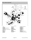
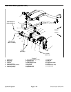
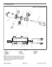
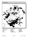
Rear Wheel Motor (Optional 3WD) Removal (Fig. 47)
1. Parkmachine on alevel surface,engage theparking
brake, lower the cutting units and stop the engine. Re-
move key from the ignition switch.
CAUTION
Before continuing further, read and become fa-
miliar with General Precautions for Removing
and Installing Hydraulic System Components in
this section.
2. Loosen,but do not remove,rear wheel lug nuts (item
5) and lock nut (item 4). Loosen lock nut at least two (2)
turns.
3. Chockbothfront wheels topreventthe machine from
moving. Lift rear wheel off t he ground using a jack and
place appropriate jack stands beneaththe frame tosup-
port the machine.
4. Remove lug nuts and rear wheel assembly.
IMPORTANT: DO NOT hit wheel hub, wheel hub
puller or wheel motor with a hammer during wheel
hub removal or installation. Hammering may cause
damage to the wheel motor.
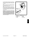
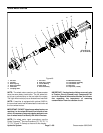
5. Use wheel hubpuller (see Special Tools in this chap-
ter) to loosen wheel hub from rear wheel motor.
6. Removelock nutand wheelhub fromrear wheelmo-
tor. Locate and retrieve woodruff key (item 23).
7. Thoroughly clean hydraulic tube ends and fittings on
rear wheel motor to prevent hydraulic system contami-
nation.
8. Label hydraulic connections at rear wheel motor for
assembly purposes.
9. Disconnect hydraulic tubes from fittings on wheel
motor. Allow lines to drain into a suitable container.
10.Put clean caps or plugs on disconnected tubes and
fittings to prevent contamination.
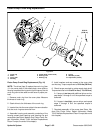
11.Support wheel motor to prevent it from falling. Re-
move two (2) cap screws (item 7), two (2) socket head
screws (item 6) and two (2) flange nuts (item 8) that se-
cure wheel motor to rear f ork. Remove rear wheel motor
and motor plate (item 2) from machine.
12.If fitting removal from wheel motor is necessary,
mark fitting orientation to allow correct assembly. Re-
move hydraulic fittings and O--rings from motor. Discard
removed O--rings.
Rear Wheel Motor (Optional 3WD) Installation (Fig.
47)
1. If fittings were removed from rear wheel motor, lubri-
cate and place new O--rings onto motor fittings. Install
fittings into motor openings making sure that fitting ori-
entationis as noted duringremoval. Tightenfittings (see
Hydraulic Fitting Installation in the General Information
section of this chapter).
2. Place m otor plate (item 2) on rear wh eel motor and
position motor to rear fork. Secure wheel motor to rear
fork withtwo (2)cap screws(item 7),two(2)sockethead
screws (item 6) and two (2) flange nuts (item 8). Torque
fasteners to 75 ft--lb (101 N--m).
3. Remove caps from disconnected hydraulic tubes.
4. Lubricateand position new O--rings to fittings onrear
wheel motor. Use labels placed during the removal pro-
cesstoproperlyinstallhydraulictubestowheelmotorfit-
tings (see Hydraulic Hose andTubeInstallationinthe
General Information section of this chapter).
5. Thoroughly clean wheel motor shaft and wheel hub
taper.
6. Install woodruff key into the wheel motor shaft key-
slot. Align wheel hub with woodruff key and slide wheel
hub onto motor shaft. Secure hub with lock n ut.
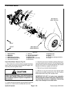
7. Installrear wheelto machine andsecurewith four(4)
lug nuts.
Failure t o maintain proper wheel lug nut and
wheel hub lock nut torque could result in failure
or loss of wheeland may result in personal injury.
WARNING
8. Lower machine to ground. Torque lock nut from 250
to 400 ft--lb (339 to 540 N--m) and wheel lug nuts from
65 to 85 ft--lb (89 to 115 N--m).
9. Check oil level in hydraulic reservoir and add correct
oil if necessary.
10.Follow Hydraulic System Start--up procedures (see
Hydraulic System Start--up in this section).
Hydraulic
System