


Greensmaster 3320/3420 Page 6 -- 81 Electrical System
The batteries used in the TriFlex electric reel drive sys-
tem are valve regulated, sealed lead acid batteries. The
batteries are maintenance free with no provision for
checking oradjusting electrolyte level. Thebatteries are
equipped with a low pressure venting system designed
to release excess gas pressure and then automatically
reseal. A low self discharge rate prevents deterioration
of battery performance during non--use or storage.
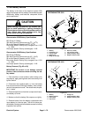
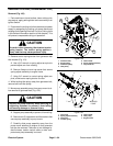
Battery Pack Removal (Fig. 97)
1. Park machine on level surface, lower cutting units,
stop engine, apply parking brake and remove key from
ignition switch.
2. Disconnect thecutting unitsfromtheelectrical power
supply by separating the cutting unit power disconnect
couplers to prevent unexpected cutting unit operation
(see Opening Electrical Circuit to Cutting Units in the
General Information section of this chapter).
3. Remove left side cover next to operator seat to allow
access to battery pack.
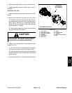
4. Using two (2) wrenches, remove flange nuts and
flange head screws that secure cables to battery termi-
nals. Remove three (3) jumper wires and position re-
maining two (2) cables away from battery terminals.
5. Remove battery clamp (item 4) to allow battery re-
moval.
6. Remove batteries from machine.
7. Inspect foam strips on battery plate and battery
clamp. Replace strips if damaged.
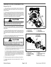
Battery Pack Installation (Fig. 97)
1. Make sure that the cutting unit power d isconnect
couplers are separated to prevent unexpected cutting
unit operation (see Opening Electrical Circuit to Cutting
Units in the General Information section of this chapter).
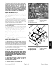
2. Place batteries onto battery plate in machine noting
positions of battery terminals (Fig. 99).
3. Secure batteries with battery clamp (item 4).
IMPORTANT: When connecting the battery pack in
the 48 volt system, make sure that battery polarity
is carefully checked. Damage to fuses or other sys-
tem components can occur if batteries are not con-
nected correctly.
4. Position and secure three (3) jumper wires and two
(2) battery cables to battery terminals. Use two (2)
wrenches to tighten fasteners.
5. Install left side cover next to operator seat.
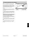
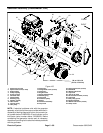
1. Front battery
2. Rear battery
3. Cable from fuse holder
4. Disconnect harness
5. Jumper wire
Figure 98
1
2
3
4
5
5
1. Cable to disconnect
2. Cable to fuse holder
3. Negative (--) terminal
4. Positive (+) terminal
5. Jumper wire
Figure 99
3
4
4
3
4
3
3
4
1
2
5
5
5
FRONT
Electrical
System