


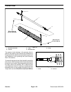

Greensmaster 3320/3420Groomer Page 9 -- 22
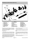
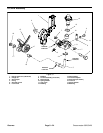
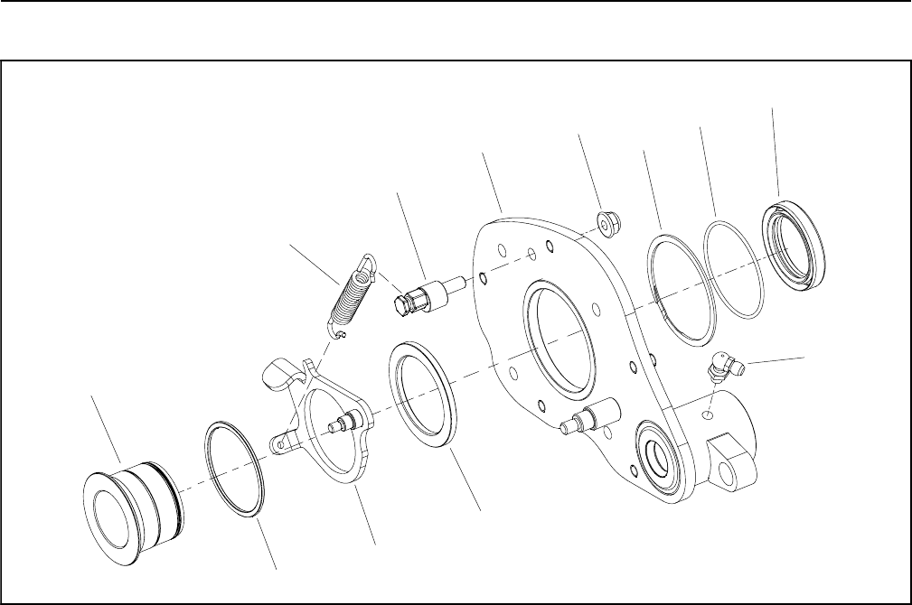
Idler Assembly (Counter Rotating Groomer Drive)
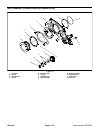
Figure 27
1. RH drive plate
2. Adjustment cam
3. Spacer
4. Idler bracket
5. Spacer
6. Reel hub
7. Retaining ring
8. O--ring
9. Flange nut
10. Extension spring
11. Grease fitting
12. Grease seal
6
3
5
4
12
9
7
8
10
1
2
11
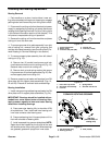
The groomer RH drive plate assembly incorporates the
idler system for engaging the groomer gear drive.
Disassembly (Fig. 27)
1. Park machine on a clean, level surface. Lower cut-
tingunits completely to theground,stop engine,engage
parking brake and remove key from the ignition switch.
2. Disconnectthecutting units from the electricalpower
supply by separating the cutting unit power disconnect
couplers (see Opening Electrical Circuitto Cutting Units
in the General Information section of this chapter). This
will prevent unexpected cutting unit operation.
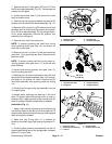
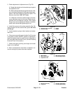
3. Make sure that handle on groomer cover is rotated
toward front of machine so that groomer drive is en-
gaged.
4. Remove groomer cover assembly and gasket from
groomer drive on right side of cutting unit (see Groomer
Cover (Counter Rotating Groomer Drive) in this sec-
tion).
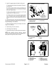
5. Remove RH drive plate assembly from right side of
cutting unit (see Grooming Reel (Counter Rotating
Groomer Drive) in this section).
6. Using Figure 27 as a guide, remove idler compo-
nents from RH drive plate as needed.
Assembly (Fig. 27)
1. Assemble idler components to RH drive plate using
Figure 27 as a guide. Make sure that retaining ring (item
7) is fully seated in groove of reel hub after assembly.
NOTE: When properly installed, the idler bracket (item
4) should pivot freely on reel hub.
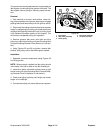
2. InstallRH drive plate assemblyto rightside ofcutting
unit (see Grooming Reel (Counter Rotating Groomer
Drive) in this section). Make sure that groomer drive
gear and grooming reel driven gear are properly
torqued. Do not install idler gears, extension spring or
groomer cover assembly to drive plate assembly at this
time.