


Greensmaster 3320/3420Groomer Page 9 -- 8
Groomer Cover (Counter Rotating Groomer Drive)
On TriFlex machines with the counter rotating groomer,
the groomer cover includes a handle which engages
and disengages the groomer drive. When the handle is
rotated toward the front of t he machine, the groomer is
engaged.
Removal
1. Park machine on a clean and level surface, lower
cutting units completely to the ground, stop engine, en-
gage parking brake and remove key from the ignition
switch.
2. Disconnectthecutting units from the electricalpower
supply by separating the cutting unit power disconnect
couplers (see Opening Electrical Circuitto Cutting Units
in the General Information section of this chapter). This
will prevent unexpected cutting unit operation.
3. If equipped, remove rear roller brush from cutting
unit (see Rear Roller Brush Removal in the Service and
Repairs section of Chapter 8 -- DPA Cutting Units).
4. Make sure that handle on groomer cover is rotated
toward front of machine so that groomer drive is en-
gaged.
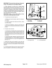
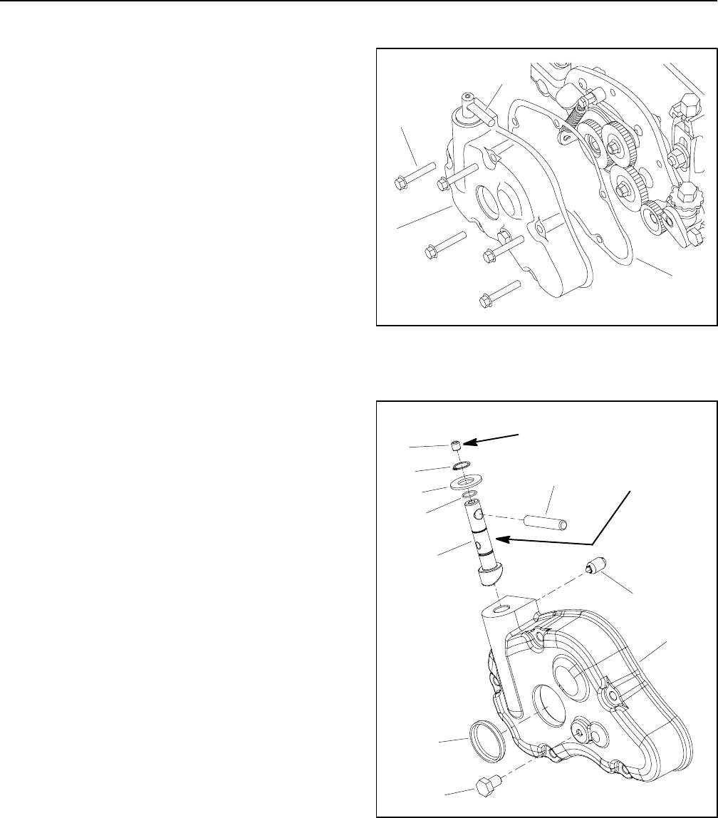
5. Remove groomer cover assembly from machine
(Fig. 5):
A. Remove five (5) flange head screws that secure
groomer cover assembly to RH drive plate.
B. Remove groomer cover assembly and gasket
from machine. Discard gasket.
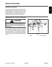
6. If necessary, remove shaft from groomer cover (Fig.
6):
A. Loosensetscrew (item9)on topofshaftand slide
handle from shaft.
B. Remove retaining ring (item 8) and thrust washer
(item5)fromshaft.
C. Remove plunger detent (item 6) from groomer
cover.
D. Slide shaft out of groomer cover. Remove and
discard O--ring (item 4) from shaft.
7. Remove grease f rom inside groomer cover and RH
drive plate on cutting unit. Thoroughly clean and inspect
all groomer drive components.
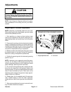
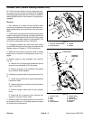
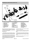
1. Groomer cover assembly
2. Screw (5 used)
3. Gasket
4. Handle
Figure 5
3
1
2
4
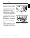
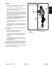
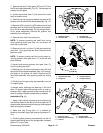
1. Groomer cover
2. Plug
3. Shaft
4. O--ring
5. Thrust washer
6. Plunger detent
7. Cap screw
8. Retaining ring
9. Set screw
10. Handle
Figure 6
6
1
4
5
8
9
3
10
2
7
Antiseize
Lubricant
Loctite #242