


Greensmaster 3320/3420Page 6 -- 16Electrical System
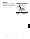
Diagnostics Screen
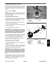
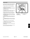
The diagnostics screen (Fig. 21) lists the various states
of machine electrical components. The diagnostics
screen should be used to check operation of machine
switches and controls.
For each of the diagnostics screen items, inputs, qualifi-
ers and outputs are identified.
The diagnostics screen includes the following:
D Engine Run identifies machine requirements to al-
lowtheenginetorun. Inputsindicatethestate oftheigni-
tion switch. Qualifiers include the joystick position,
functionalcontrol leverposition, seat switchand parking
brake position. Outputs consist of OK Run and RTR
(Greensmaster 3320 relay to run) / ETR(Greensmaster
3420 energize to run).
D Glowplugsidentifiesmachinerequirements toallow
thediesel engine glowplugs tobeenergized. Inputs indi-
cate the state of the ignition switch. Outputs indicate
whether the glowplugs are energized.
D Fan identifies machine requirements to allow the
cooling fan to be energized on Greensmaster 3420 ma-
chines. Inputs indicate the state of the engine coolant
and hydraulic oil (optional) temperature senders. Out-
puts indicate whether the fan is energized.
D S1 identifies machine requirements to allow hydrau-
lic lift control manifold solenoid coil S1 (raise/lower en-
able) to be energized. Inputs indicate the state of the
joystick raise and lower switches. Qualifiers lists the
joystick position. Outputs indicate whether solenoid S1
is energized.
D S2 identifies machine requirements to allow hydrau-
lic lift control manifold solenoid coil S2 (lower) to be en-
ergized. Inputs indicate the state of the joystick lower
switch. Qualifiers identify the three (3) second time-
frame to lower the cutting units. Outputs indicate wheth-
er solenoid S2 is energized.
D S3 identifies machine requirements to allow hydrau-
lic lift control manifold solenoid coil S3 (raise or lower)
to be energized. Inputs indicate the state of the joystick
raise andlower switches.Qualifiers identify thethree (3)
second timeframe plus the delay for the center cutting
unit to raise or lower the cutting units. Outputs indicate
whether solenoid S3 is energized.
D S4 identifies machine requirements to allow hydrau-
lic lift control manifold solenoid coil S2 (raise or lower)
to be energized. Inputs indicate the state of the joystick
raise andlower switches.Qualifiers identify thethree (3)
second timeframe plus the delay for the center cutting
unit to raise or lower the cutting units. Outputs indicate
whether solenoid S4 is energized.
D Reels Enable identifies whether the TEC output ex-
ists to energize the e--reels enable r elay. This relay
provides 48V logic power to the reel motors and gener-
ator.
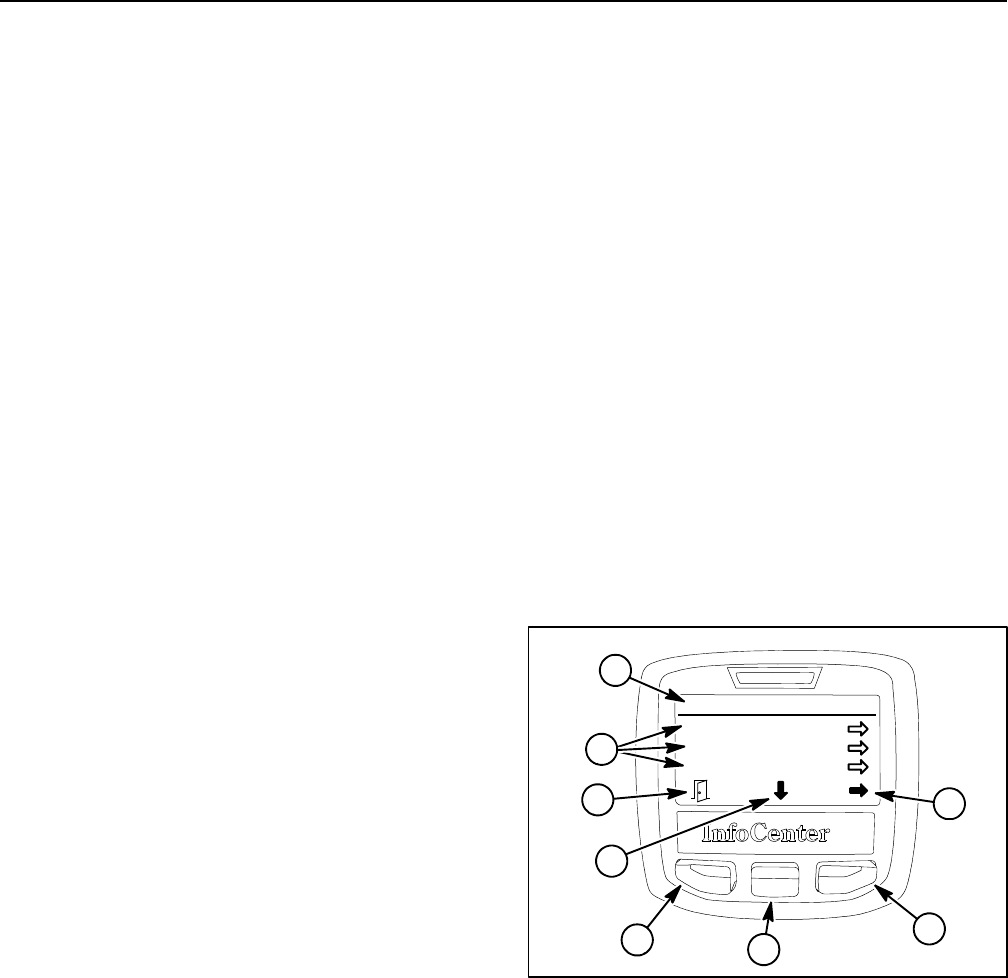
To return to the main menu screen from the diagnostics
screen, press the back button (left button).
1. Diagnostics menu
2. Diagnostics items
3. Move to menu items
4. Choose menu item
5. Back button
Figure 21
Diagnostics
Engine Run
Glowplugs
Fan
ON
OFF
ON
1
5
3
4
5
2
3
4