


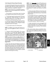


Greensmaster 3320/3420 Page 6 -- 27 Electrical System
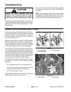
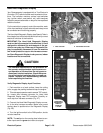
5. The “INPUTS DISPLAYED” LED, on lower right col-
umn ofthe Hand HeldDiagnostic Display,should beillu-
minated. If the green “OUTPUTS DISPLAYED” LED is
illuminated, p ress the toggle button on the Diagnostic
Display to change to “INPUTS DISPLAYED” LED.
6. The Hand Held Diagnostic Display will illuminate the
LED associated with each of the inputs when that input
is in the position identified on the Diagnostic Display
overlay. Individually, change the position of each of the
inputs (i.e.sit on seat, move joystick, etc.),and note that
the appropriate LED on the Diagnostic Display t oggles
on and off when the input state is changed (see Hand
Held Diagnostic Display Inputs and LED Operation
chart on next page). Repeat f or all i nputs that can be
changed by hand.
7. If appropriate LED does not toggle on and off when
input state is changed, check all wiring and connections
to the switch for that input and/or test switch (see Com-
ponent Testing in this chapter). Replace all defective
switches and repair any damaged wiring.
NOTE: The LEAK DETECTOR controller input is only
used on Greensmaster 3320 machines that are
equipped with the Turf Guardian
TM
Leak Detector Sys-
tem.TheCOOLANT TEMP,ALT FAULTandHYDTEMP
controller inputs are only used on Greensmaster 3420
machines.
NOTE: On Greensmaster 3420 machines, the ALT
FAULT controller input cannot be reliably tested by
grounding the harness leads at the alternator. If the al-
ternator is faulty, a TEC controller fault should have
been detected. On machines with serial number below
312000000, the fault code will be retrieved using the
diagnostic light (see Diagnostic Light (Serial Number
Below 312000000) in this section). Use the InfoCenter
Display for fault retrieval on machines with serial num-
ber above 312000000 (see InfoCenter Display (Serial
Number Above 312000000) in this chapter).
NOTE: When the ignition switch is in the OFF position,
all Hand Held Diagnostic Display LED’s should be OFF.
8. After input function testing is completed, disconnect
theHandHeldDiagnosticDisplay fromwire harness.In-
stall cap into wire harness connector. Lower and secure
seat.
Electrical
System