


Rev. A
Greensmaster 3320/3420Page 6 - 66Electrical System
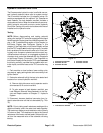
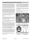
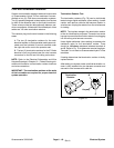
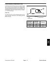
Cutting Reel Motors
The three (3) cutting reel motors are identical 48 VDC,
brushless, permanent magnet motors. Each motor has
its own integral invertor and on- board controller.
Because the cutting reel motors used on the machine
are identical, motors from different cutting units can be
exchanged. If the problem follows a motor to the new
cutting unit, the motor is likely the issue. If the problem
remainswith thecutting unit, theissueis likely dueto the
cutting unit, electrical components or wiring to that cut-
ting unit.
NOTE: Before considering that cutting reel motor ser-
vice work is necessary, check for any existing fault
codes that indicate problems with a reel motor (see
Fault Codes in the Troubleshooting section of this chap-
ter). Ifa cutting reel motor isfaulty,there will likelybe nu-
merous fault codes that are listed by t he InfoCenter
display.
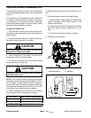
Testing
1. Park machine on level surface, lower cutting units,
stop engine, apply parking brake and remove key from
ignition switch.
2. Separate system components from the 48 VDC bat-
tery pack by separating the cutting unit power discon-
nect couplers (see Opening Electrical Circuit to Cutting
Units in theGeneral Information section of this chapter).
This will prevent unexpected cutting unit op eration.
3. Locate cutting reel motor cable electrical connec-
tions at machine wireharness for motorthat isto betest-
ed.
IMPORTANT: When disconnecting reel motor cable
connectors, take care to not damage the cable or
connectors. The reel motor cable is not available as
a separate r eplacement p art.
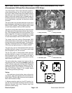
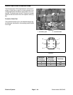
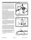
4. Carefully disconnect two (2) reel motor cable con-
nectors from machine wire harness (Fig. 85).
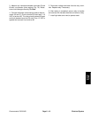
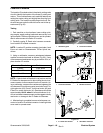
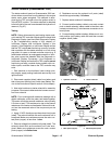
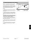
5. Using a multimeter, measure resistance between 48
VDCgroundterminal(blackwire)in the2 wireconnector
and location ID terminal (blue wire) in 4 wire connector
(Fig. 86). Resistance should be approximately 18.8
K- ohms.
6. If measured resistance isincorrect, consider thatthe
cutting reel motor is faulty.
NOTE: If cutting reel motor removal, installation, disas-
sembly or assembly information is needed, see Cutting
Reel Motor and Cutting Reel Motor Service in the Ser-
vice and Repairs section of this chapter.
7. After testing is completed, secure two (2) reel motor
cable connectors to machine wire harness connectors.
8. Connect the cutting unit power disconnect couplers
together before operating the machine.
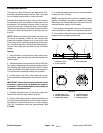
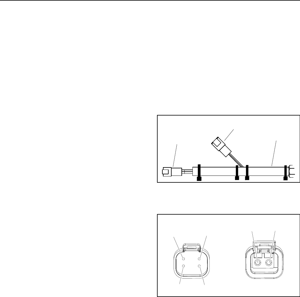
1. Cable from motor
2. 4 wire connector
3. 2 wire connector
Figure 85
2
3
1
1. 48 VDC power (red)
2. 48 VDC ground (black)
3. 48 VDC logic (white)
4. Location ID (blue)
5. CAN Low (yellow)
6. CAN High (green)
Figure 86
2
3
1
4
5
6