


Greensmaster 3420Page 4 -- 16Diesel Engine
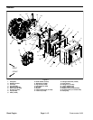
Engine
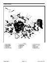
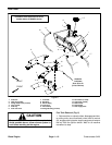
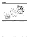
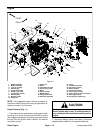
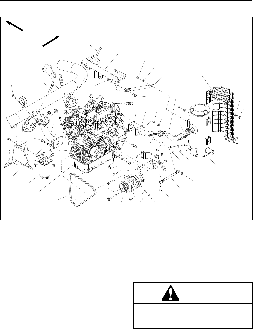
Figure 11
18
16
16
10
17
1
2
3
6
8
9
11
13
5
7
12
14
15
4
3
6
13
13
FRONT
RIGHT
1. Engine assembly
2. Muffler assembly
3. Lock nut (4 used)
4. Exhaust pipe
5. Flange head screw
6. Flange nut (4 used)
7. Lock washer (3 used)
8. Exhaust plate
9. Exhaust gasket
10. Flange nut
11. Flange nut
12. Brace
13. Flat washer (8 used)
14. Cap screw (4 used)
15. Brace
16. Spring (4 used)
17. Muffler shield
18. Flange head screw
19. Alternator assembly
20. V--belt
21. Fuel/water separator
22. Cap screw (2 used)
23. Engine support
24. Cap screw (4 used)
25. Lock washer (4 used)
26. Lock washer (ground connection)
27. Rear engine mount
28. R--clamp (air intake hose)
19
20
21
22
22
23
24
26
25
27
28
18
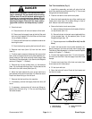
NOTE: This suggested engine removal procedure al-
lows the hydraulicpump, bellhousing andgenerator as-
sembly to remain in the machine.
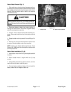
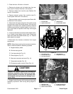
Engine Removal (Fig. 11)
1. Parkmachineon alevelsurface, disengage and low-
er cutting units, move functional control lever to neutral
(N), engage parking brake, stop the engine and remove
the key from the ignition switch. Wait for all machine
movement to stop.
CAUTION
The engine, radiator, exhaust system and hy-
draulic system may be hot. To avoid possible in-
jury, allowmachine tocool before working onthe
engine.
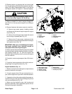
2. Disconnect b attery cables from battery. Disconnect
negative battery cable first and positive cable last.