


Greensmaster 3320/3420Groomer Page 9 -- 10
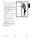
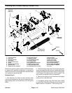
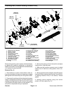
Grooming Reel (Forward Rotating Groomer Drive)
Figure 8
1. Lock nut (4 used)
2. Drive cover
3. Groomer drive belt
4. Drive pulley
5. Shoulder bolt (2 used)
6. Spring
7. RH drive plate assembly
8. Groomer shim
9. RH groomer arm assembly
10. Cap screw (2 used)
11. Bushing (2 used)
12. Spring washer (2 used)
13. Lock nut (2 used)
14. LH support plate
15. LH groomer arm assembly
16. Special washer (2 used)
17. Rear roller height shim
18. Socket head screw (4 used)
19. Driven pulley
20. HOC screw (2 used)
21. HOC nut (2 used)
22. Plow bolt (2 used)
23. Grooming reel assembly
24. Front roller assembly
25. RH cutting unit sideplate
26. LH cutting unit sideplate
27. O--ring
FRONT
RIGHT
Antiseize
Lubricant
100 ft--lb
(135 N--m)
1
2
3
4
5
6
7
8
9
10
11
12
13
14
15
16
17
18
19
1
20
21
22
23
24
11
12
13
25
26
27
17 to 21 ft--lb
(24 to 28 N--m)
Remove the grooming reel to replace individual blades,
to replace worn groomer components, to reverse the
blades onthe shaft (ifnot equippedwith carbide blades)
or to replace the grooming shaft.
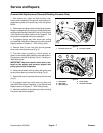
Removal (Fig. 8)
1. Park machine on a clean and level surface, lower
cutting units completely to the ground, stop engine, en-
gage parking brake and remove key from the ignition
switch.
2. Disconnectthecutt ing unitsfromthe electricalpower
supply by separating the cutting unit power disconnect
couplers (see Opening Electrical Circuit to Cutting Units
in the General Information section of this chapter). This
will prevent unexpected cutting unit operation.
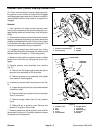
3. Remove the cutting unit from the machine and place
cutting unit on a flat work area.
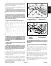
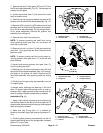
4. If equipped, remove rear roller brush from cutting
unit (see Rear Roller Brush Removal in the Service and
Repairs section of Chapter 8 -- DPA Cutting Units).