


Greensmaster 3320/3420 Hydraulic SystemPage 5 -- 47
Flush Hydraulic System
IMPORTANT: Flush the hydraulic system any time
there is a severe component failure or the system is
contaminated (oil appears milky or black or con-
tains metal particles).
IMPORTANT: Flush hydraulic system when chang-
Ing from petroleum base hydraulic fluid. Operate
machine under normal operating conditions for at
least four (4) ho urs before draining.
1. Parkmachine on alevel surface,engage theparking
brake, lower the cutting units and stop the engine. Re-
move key from the ignition switch.
CAUTION
Before continuing further, read and become fa-
miliar with General Precautions for Removing
and Installing Hydraulic System Components in
this section.
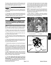
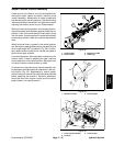
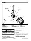
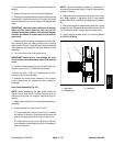
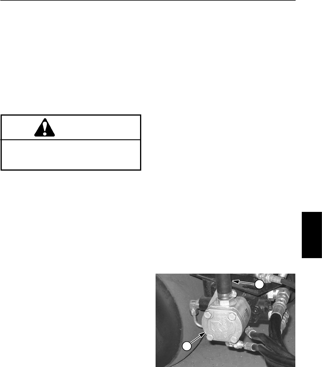
2. Clean area around gear pump suction (inlet) hose
(Fig. 31). Clamp pump inlet hose. Remove inlet hose
from gear pump, release clamp and drain reservoir into
a suitable container.Drain entire hydraulic system while
making sure lift cylinders, hydraulic hoses, hydraulic
tubes and all other components are drained from low
points while the system is warm.
3. Clean oil filter mounting area. Remove filter and
drain into a suitable container. Discard filter.
4. Inspectandclean reservoir(see Hydraulic Reservoir
in this section).
5. Make sure filter mounting surface is clean. Apply
cleanhydraulic oil to gasketon the new filter. Screw filter
on until gasket contacts mounting plate, then tighten fil-
ter an additional 3/4 turn.
NOTE: Use only hydraulic fluids (including biodegrad-
able fluid) specified in the Traction Unit Operator’s
Manual. Other fluids could cause system damage.
6. Connect all hydraulic hoses and lines that were dis-
connected prior to system draining (see Hydraulic Hose
and Tube Installation in the General Information section
of this chapter).
7. Fill hydraulic reservoir with new hydraulic oil.
8. Disconnect appropriate electrical component(s) to
prevent the engine from starting:
A. On machines with gasoline engine, disconnect
both spark plug wires from spark plugs.
B. On machines with diesel engine, disconnect wire
harness electrical connector from the engine fuel
stop solenoid.
9. Turn ignition key switch and engage starter for ten
(10) seconds to the prime pump. Return ignition switch
to off andwait one (1)minute to allow starter tocool. Re-
peat step a second time.
10.Reconnect engine electrical component(s) that were
disabled in step 8 above.
11.Startengine and letit run atlow idle speed for amini-
mum of two (2) minutes. Increase engine speed to high
idle for a minimum of one (1) minute under no load.
12.Raise and lower cutting units several times.
13.Shut off e ngine and check for hydraulic oil leaks.
Check oil level in hydraulic reservoir and add correct oil
if necessary.
14.Operate the machine for two (2) hours under normal
operating conditions.
15.Check condition of hydraulic oil. If the new fluid
shows anysigns of contamination orif you are changing
to biodegradable fluid, repeat steps 1 through 14 again.
16.Assume normal operation and follow recommended
maintenance intervals.
Figure 31
1
2
1. Gear pump 2. Suction (inlet) hose
Hydraulic
System