


Greensmaster 3320/3420 Hydraulic SystemPage 5 -- 75
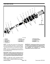
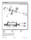
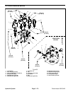
NOTE: Theports onthe lift control ma nifold a remarked
for easy identification of components. Example: S1 is
the solenoid valve and P is the supply port (see Hydrau-
lic Schematic to identify the function of the hydraulic
lines and cartridge valves at each port location).
WARNING
If lift manifold is attached to machine, make sure
that cutting units are fully lowered before loos-
ening hydraulic lines or cartridge valves from lift
manifold. If cutting units are raised as compo -
nents are loosened in manifold, cutting units
may drop unexpectedly.
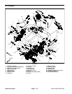
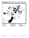
Removal (Fig. 51)
1. Park machine on a level surface, engage parking
brake, lower cutting units and stop the engine.
2. Remove right side cover next to operator seat to al-
low access to lift control manifold.
CAUTION
Before continuing further, read and become fa-
miliar with General Precautions for Removing
and Installing Hydraulic System Components in
this section.
3. Thoroughly clean hydraulic line ends and fittings on
lift control manifoldto prevent hydraulic systemcontam-
ination.
4. Label all hydraulic and electrical connections for as-
sembly purposes.
5. Disconnect wire harness connectors from solenoid
valve coils on lift manifold.
IMPORTANT: Before disconnecting hydraulic lines
from the manifold fittings, make sure each hose or
tube is labeled to ensure it can be connected to the
correct manifold fitting/port.
6. Disconnect hydraulic hose and tube assemblies and
remove their respective O--rings from the manifold fit-
tings. Allow hoses and tubesto drain into asuitable con-
tainer. Install clean caps or plugs to hoses and manifold
fittings to prevent contamination.
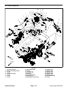
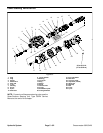
7. Remove two (2) flange head screws (item 16) that
secure liftmanifold tomachine frame.Remove manifold
assembly from the machine.
IMPORTANT: Before removing any hydraulic fitting
from thehydraulic manifold, makesure the position
of fitting is observed and recorded to ensure proper
fitting installation.
IMPORTANT: A flow control orifice is placed be-
neath hydraulic fittingsin lift control manifold ports
C4 and C6.If either of these fittings is removed from
the lift junction manifold, make sure to remove ori-
fice and label its position for assembly purposes.
Also note location of groove in orifice for assembly
purposes.
8. If hydraulic fittings are to be removed from manifold,
mark fitting orientation to allow correct assembly. Re-
move hydraulic fittings and O--rings from manifold. Dis-
card removed O--rings.
Installation (Fig. 51)
IMPORTANT: If installing an orifice inmanifold port,
make sure that orifice is flat in the base of the man-
ifold port. Manifold damage is possible if the orifice
is cocked in the cavity.
1. If fittings were removed from junction manifold, lubri-
cate and place new O --rings onto fittings. Install fittings
into manifold openings making sure that orifice (ports
C4 and C6) is correctly placed before threading fitting
into manifold. Use marks made during the removal pro-
cess t o correctly orientate fittings. Properly tighten fit-
tings (see Hydraulic Fitting Installation in the General
Information section of this chapter).
2. Position manifold assembly to the machine frame.
Secure assembly to the frame with two (2) flange head
screws (item 16).
3. Remove caps and plugs from disconnected hydrau-
lic lines and manifold fittings.
4. Lubricate and position new O--rings to fittings on
manifold. Use labels placed during the removal process
to properlyinstall hydraulic lines to manifold fittings (see
Hydraulic Hose and Tube Installation in the General In -
formation section of this chapter).
5. Connect wire harness connectors to solenoid valve
coils on lift manifold.
6. Install right side cover.
Hydraulic
System