


Greensmaster 3320/3420
DPA Cutting Units
Page 8 -- 33
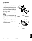
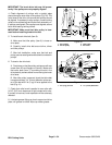
Disassembly (Fig. 38)
1. Position machine on a clean and levelsurface, lower
cutting units, stop engine, engage parking brake and re-
move key from the ignition switch.
2. To remove roller brush from b rush shaft:
A. Loosen set screw in the bearing locking collar on
left side of brush shaft.
B. Usingblindholeinbearinglockingcollaras anim-
pact point, unlock collar by striking it with a punch in
the opposite direction of brush rotation.
C. Remove the LH brush support (item 15), bearing
and locking collar from brush shaft and cutting unit.
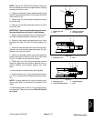
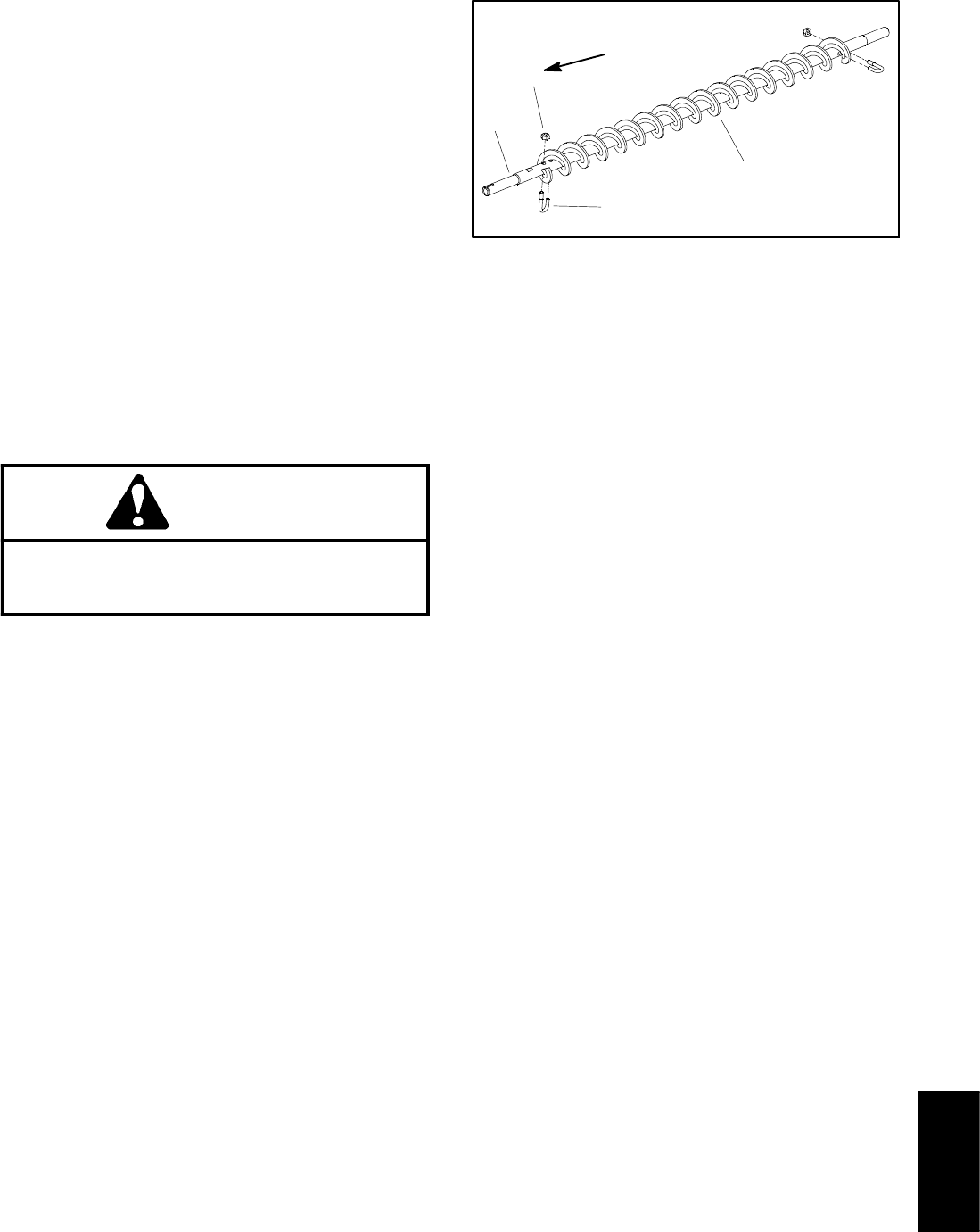
D. Removelock nutand J--bolt fromboth ends ofthe
brush (Fig. 39).
E. While rotating brush, slide brush from the shaft.
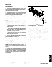
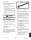
CAUTION
Contact with the reel or other cutting unit parts
can result in personal injury. Use h eavy gloves
when handling the cutting reel.
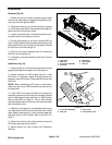
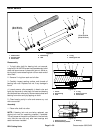
3. To remove roller brush drive belt (item 2):
A. Loosen cap screw (item 22) and flange nut (item
8) that secure idler pulley assembly (item 6) to drive
plate.
B. Move idler pulley to loosen drive belt.
C. Carefullyremove drivebelt fromdrive, driven and
idler pulleys.
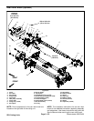
4. Disassemble roller brush components as necessary
using Figure 38 as a guide.
Assembly (Fig. 38)
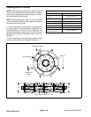
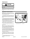
1. If roller brush was removed from brush shaft, slide
brush onto shaft while rotating brush. Secure brush to
shaft with two (2) J--bolts and lock nuts. Make sure that
the J-- bolts are installed with the threaded portion on the
outside of the brush (Fig. 39). Torque lock nuts from 20
to 25 in--lb (2.3 to 2.8 N--m).
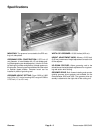
1. Roller brush shaft
2. J--bolt
3. Roller brush
4. Lock nut
Figure 39
20 to 25 in--lb
(2.3 to 2.8 N--m)
1
2
3
4
2. Assemble roller brush components using Figure 38
as a guide and the following assembly notes:
A. The screws (item 12) that are used to secure the
cover (item 1), driven pulley (item 10) anddrive plate
(item 9) have a threadlock feature to prevent the
screws from loosening. If original screws are being
re--used during assembly, apply Loctite #242 (or
equivalent) to threads of screws.
B. .Apply a light coating of grease to O--ring (item
18) before installing on drive plate flange. Make sure
that O--ring is correctly positioned in groove in
flange.
C. Apply antiseize lubricant to threads of cap screw
(item 5) that retains drive pulley (item 3). Torque cap
screw from 70 to 80 in--lb (8 to 9 N--m) to secure
drive pulley to pulley driver.
D. Secure driven pulley (item 10) to brush shaft with
threadlock screw (item 12). Torque screw from 130
to 140 in-- lb (15 to 16 N--m).
E. Secure pulley driver (item 4) to cutting reel shaft
with 100 ft--lb (136 N--m) torque.
3. If either of the bearing locking collars was loosened,
tighten locking collar onto brush shaft:
A. Slide locking collar outward on brush shaft onto
the bearing collar. Rotate locking collar by hand in
the direction of normal brush rotation until the collar
is tight on the shaft.
B. Usingblindholeinbearinglockingcollar asanim-
pact point, lock collar by striking it with a punch in the
normal direction of brush rotation.
C. Tighten set screw in locking collar to secure the
bearing assembly to the brush shaft.
DPA Cutting
Units