


Greensmaster 3320/3420
DPA Cutting Units
Page 8 -- 21
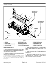
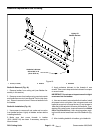
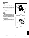
Cutting Reel Assembly Removal (Fig. 22)
CAUTION
Contact with the reel, bedknife or other cutting
unit parts can result in personal injury. Use
heavy gloves when removing the cutting reel.
1. Position machine on a clean and levelsurface, lower
cutting units, stop engine, engage parking brake and re-
move key from the ignition switch.
2. Remove the cutting unit from the machine and place
cuttingunitonaflatworkarea.
3. Ifcutting unitis equipped withan optionalgroomer or
rear roller brush, remove drive components for those
options from cutting unit. See Service and Repairs sec-
tion of Chapter 9 -- Groomer for information on groomer.
See Rear Roller Brush in this section for information on
rear roller brush.
4. Remove two (2) cap screws and nuts that secure
weight (item 10) to the RH side plate. Remove weight
assembly (items 10 and 20) from the cutting unit. Re-
move and discard O--ring from weight.
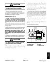
5. If bearings or seals are to be removed from cutting
reel, put a block of wood betweenthe cutting reel blades
to prevent the reel from rotating. Loosen bearing lock
nut (RHthreads) and reel nut (LH threads)to allow easi-
er removal after reel assembly is removed from cutting
unit (Fig. 23).
6. Remove the bedbar pivot bolt and washers from the
LH side plate. Note locationof plastic and steel washers
for assembly purposes (see Bedbar Removal in this
section).
7. Loosen fasteners that secure front and rear rollers to
LHsideplate( see FrontRollerRemovalandRear Roller
Removal in this section).
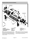
8. Remove washer head screws (item 3) that secure
crosslink (item 15) to pitch arms. Remove crosslink.
9. Support cutting reel to keep it from shifting or falling.
10.Removeshoulder b olts(item 4) andflange nuts(item
5) that secure the LH side plate to the cutting unit cross-
member. Remove the LH side plate from the reel shaft,
rollers, bedbar and cutting unit crossmember. Locate
and remove flat wirespring (item 14).Remove pitcharm
(item 7) from side plate.
11.Carefully slide the cutting reel assembly (with
flocked seals, reelbearings, bearing lockscrew and reel
nut) from the RH side plate.
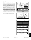
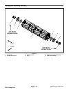
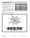
1. Cutting reel
2. Flocked seal (2 used)
3. Bearing (2 used)
4. Plug
5. Bearing lock screw
6. Reel nut (LH threads)
7. Reel groove location
Figure 23
1
2
3
4
5
3
2
7
6
(Right Hand Threads)
90 to 110 ft--lb
(123 to 149 N--m)
90 to 110 ft--lb
(123 to 149 N--m)
(Left Hand Threads)
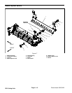
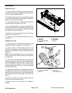
Cutting Reel Assembly Installation (Fig. 22)
1. Thoroughly clean side plates and other cutting unit
components. Inspect side plates and pitch arms for
wear or damage and replace components if needed.
2. Make sure that flocked seals, reel bearings, bearing
lock screw and reel nut are properly positioned on cut-
tingreel(seeReelAssembly Serviceinthissection).Ap-
ply thin coat of grease to outside of bearings on cutting
reel to ease reel installation.
CAUTION
Contact with the reel, bedknife or other cutting
unit parts can result in personal injury. Use
heavy gloves when installing the cutting reel.
3. Position the cutting unit on a flat work area. The roll-
ers, bedbar and cutting unit crossmember should be at-
tached to RH side plate. Make sure that pitch arm (item
7) is fitted to RH side plate.
4. Carefully slide the cutting reel assembly (with
flockedseals, reelbearings, bearing lockscrew andreel
nut) into theRH side plate. Makesure that bearing isful-
ly seated into side plate.
5. PlaceflatwirespringintobearingboreofLHside
plate. Carefully slide the LH side plate with pitch arm
ontothe cutting reel assembly,frontrollerand rearroller.
Make sure that side plate is fully seated onto bearing on
reel shaft.
DPA Cutting
Units