


Greensmaster 3320/3420Page 6 -- 84Electrical System
Generator Drive Belt (Greensmaster 3320)
Removal (Fig. 100)
1. Park machine on a level surface, lower cutting units,
stop engine, apply parking brake and remove key from
ignition switch.
2. Disconnectthecutting units from the electricalpower
supply by separating the cutting unit power disconnect
couplers (see Opening Electrical Circuitto Cutting Units
in the General Information section of this chapter). This
will prevent unexpected cutting unit operation.
CAUTION
Be careful when removing idler bracket torsion
spring tension. The torsion spring applies a
heavy load that may cause personal i njury.
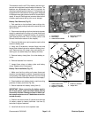
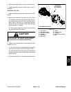
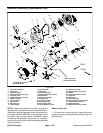
3. Remove torsion spring tension from generator belt
idler bracket (Fig. 101):
A. Use a 3/4” wrench on spring adjust arm pivot to
prevent a djust arm from rotating.
B. Remove flange nut and cap screw that secure
spring adjust assembly to engine frame.
C. Using 3/4” wrench to control spring adjust arm
pivot, allow torsion spring tension to relax.
4. While holding idler pulley away from generator belt,
remove belt from idler pulley.
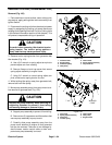
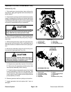
5. Move pump assembly away from pump mount to al-
low removal of generator belt (Fig. 102):
CAUTION
Support the pump assembly when removing its
supporting fasteners to prevent it from falling
and causing damage or personal injury.
A. Support pump assemblyto prevent it from falling.
B. Remove two(2) cap screwsand flat washersthat
secure pump assembly to pump mount.
C. Carefully slide pump assembly away from the
pump mount attached to engine so that generator
belt can be removed. Take care to not damage hy-
draulic hoses, traction control cable or other com-
ponents as pump assembly is moved.
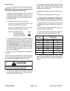
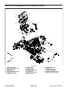
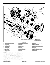
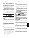
1. Generator belt
2. Engine pulley
3. Generator pulley
4. Idler pulley
5. Idler bracket
6. Spring adjust assembly
7. Cap screw/nut
Figure 100
3
2
4
1
5
7
6
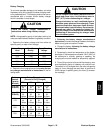
1. Cap screw
2. Spring adjust assembly
3. Flange nut
4. Torsion spring
5. Idler bracket
6. Idler pulley
7. Engine frame
Figure 101
3
4
5
6
1
2
WRENCH
POINT
7