


Greensmaster 3320/3420 Page 6 -- 51 Electrical System
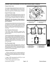
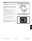
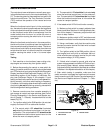
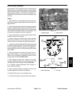
Neutral and Mow Switches
The neutral and mow switches are normally open prox-
imity switches that mount to the console assembly (Fig.
57). The sensing plate for these switches is a tab on the
functional control lever. The Toro Electronic Controller
(TEC) m onitors the operation of the neutral and mow
switches.
When the functional control lever is in the neutral posi-
tion, thetabonthe leveris positionednearthe targetend
of the neutralswitch causing the switchto close. Thetab
on the functional control lever is moved away from the
neutral switch when the lever is in either the mow or
transport position causing the switch to be in its normal
open state.
When the functional control lever is in the mow position,
the tab on the lever is positioned near the target end of
the mow switch causing the switch to close. The tab on
the functional control leveris movedaway fromthe mow
switch when the lever is in either the neutral ortransport
position causing the switch to be in its normal open
state.
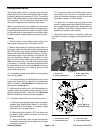
Testing
1. Park machine on level surface, lower cutting units,
stop engine and remove key from ignition switch.
2. Before disconnecting the neutral or mow switch for
testing, the switch and its circuit wiring should be tested
asaTEC electricalinputusingthe Hand HeldDiagnostic
Display (see Hand Held Diagnostic Display in the Trou-
bleshooting section of this chapter) or InfoCenter Dis-
play (see InfoCenter Display in this chapter). If input
testingverifies that the switchand circuitwiring arefunc-
tioning correctly, no further switch testing is necessary.
If, however, input testing determines that the switch and
circuit wiring are not functioning c orrectly, proceed with
the following switch testing procedure.
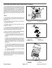
3. Remove console cover from console assembly to
gain access to neutral and mow switches (see Control
Console Disassembly in the Service and Repairs sec-
tion of Chapter 7 -- Chassis). Locate switch that is to be
tested (Fig. 57).
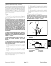
4. Turn ignition switch to the RUN position (do not start
engine) and check LED on cable end of switch.
A.TheneutralswitchLEDshould be illuminated
only when the functional control lever is in the neu-
tral position. The neutral switch LED should not be
illuminated when the functional control lever is in the
either the mow or transport position.
B. The mow switchLED should be illuminated only
when the functional control lever is in the mow posi-
tion.Themow switchLED shouldnot beilluminated
when the functional control lever is in the either the
neutral or transport position.
5. IfthetestedswitchLEDdidnotfunctioncorrectly:
A. Make sure that switch is properly adjusted (see
Neutral and Mow Switches in the Adjustments sec-
tion of this chapter). If necessary, adjust switch and
return to step 4 above.
B. Make sure ignition switch is OFF and disconnect
theswitch connectorfrom the machine wireharness.
C. Using a multimeter, verify that the machine wire
harness connector terminal for black wire is closed
(continuity) to ground.
D. Turn ignition switch to the RUN position (do not
start engine) and verify with a multimeter that ma-
chine wire harness connector terminal for pink wire
has system voltage (12 VDC) present.
E. If black wire is closed to ground, pink wire has
system voltage present and switchLED didnot func-
tion correctly (step 4 above), replace tested switch.
Adjust switch after installation (see Neutral and Mow
Switches in the Adjustments section of this chapter).
6. After switch testing is complete, make sure that
switch connector is plugged into machine wire harness.
Install console cover (see Control Console Assembly in
the Service and Repairs section of Chapter 7 -- Chas-
sis).
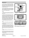
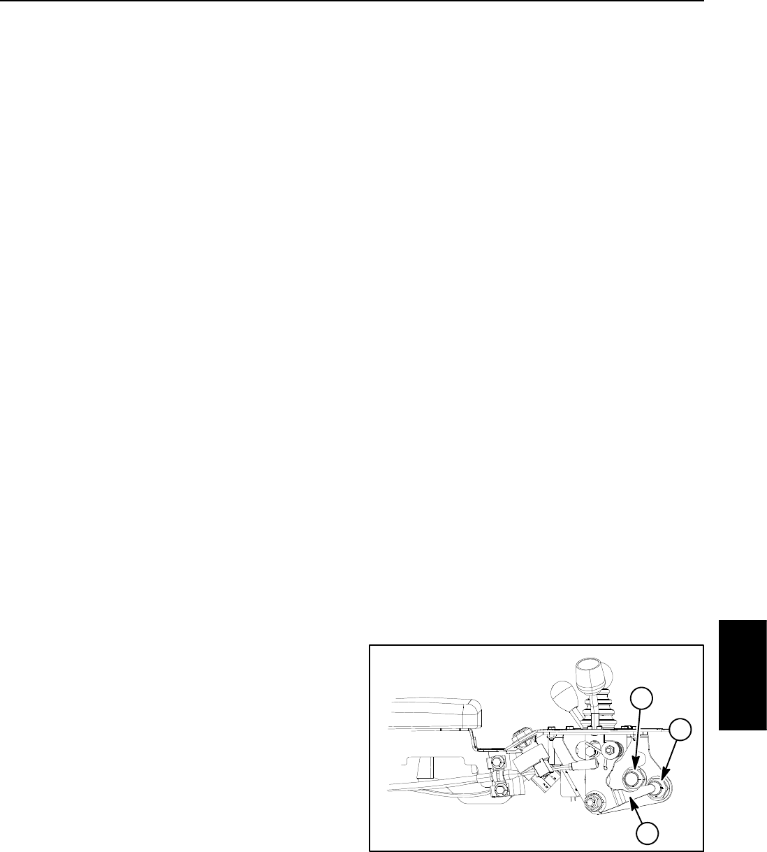
Figure 57
1. Functional lever tab
2. Mow switch
3. Neutral switch
2
1
3
Electrical
System