


Groundsmaster 4000--D Hydraulic System (Rev. B)Page 4 -- 65
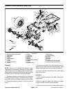
5. Apply Loctite #242 or equivalent to set screw (18)
and install into control housing. Adjust set screw until it
bottoms out on input shaft and back out one--quarter
turn.
6. Install wiper seal on input shaft.
7. Install new o--r ing (2) onto plug and install plug. Ad-
just plug until there is no end play in the valve spool with
input shaft held stationary. Secure plug in place with set
screw (24). Torque set screw from 17 to 26 in--lb (2 to 3
N--m).
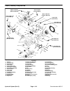
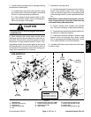
Disassembly -- Neutral Switch
1. Loosenset screw (17)in adapter and removeneutral
switch from adapter.
2. Remove adapter from control housing.
3. Remove pin, ball, and o--rings (11 & 16) from adapt-
er.
Reassembly -- Neutral Switch
1. Install new o--ring (11) onto adapter and new o--ring
(16) onto pin.
2. Install ball and pin into adapter. Lubricate with petro-
leum jelly to hold in place during installation.
3. Install adapter into control housing. Torque from 44
to52ft--lb(60to70N--m).
4. Apply Loctite #222 or equivalent to threadsof neutral
switch and install switch into adapter. The adjustment
procedure for the switch are as follows.
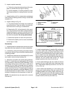
A. Install switch, while moving link back and forth,
until “detent” action is detected. Back out the switch
until the “detent” action is very slight.
B. Attach the leads from a test light to the s witch ter-
minals. Note: A multimeter could be used instead of
a test light.
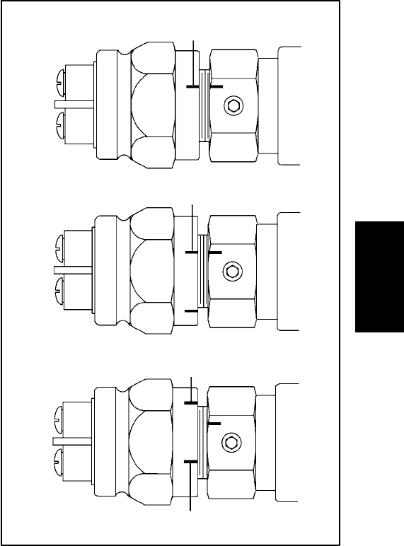
C. Move the link out of the detent position. The test
light will go on. Screw in the switchuntil the light goes
off. Mark this as position “A” (Fig. 48). Move the link
to the detent position and the test light should come
back on.
D. Leavingthe link in the detent position, the lightwill
remain on. Screw in the switch until the light goes off.
Mark this position “B”.
E. Unscrew the switch one third of the distance be-
tween “B” and “A”. Install and tighten the set screw
(17) in one of the upper quadrants of the hex of the
switch adapter (Fig. 48). Torque set screw from 28 to
34 in--lb (3.2 to 3.8 N--m).
5. Test the switch by moving the control arm to the det-
ent position, the lightshould beon. Move the controlarm
out of detent, the light should go off.
6. Remove test light and put servo control assembly
into operation.
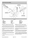
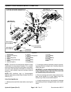
Step 4--C
Step 4--D
Step 4--E
Reassembly
Reassembly
Reassembly
“B”
“B”
“A”
“A”
Figure 48
Hydraulic
System