


Rev. E
Groundsmaster 4000−DCutting Units
Page 8 − 10
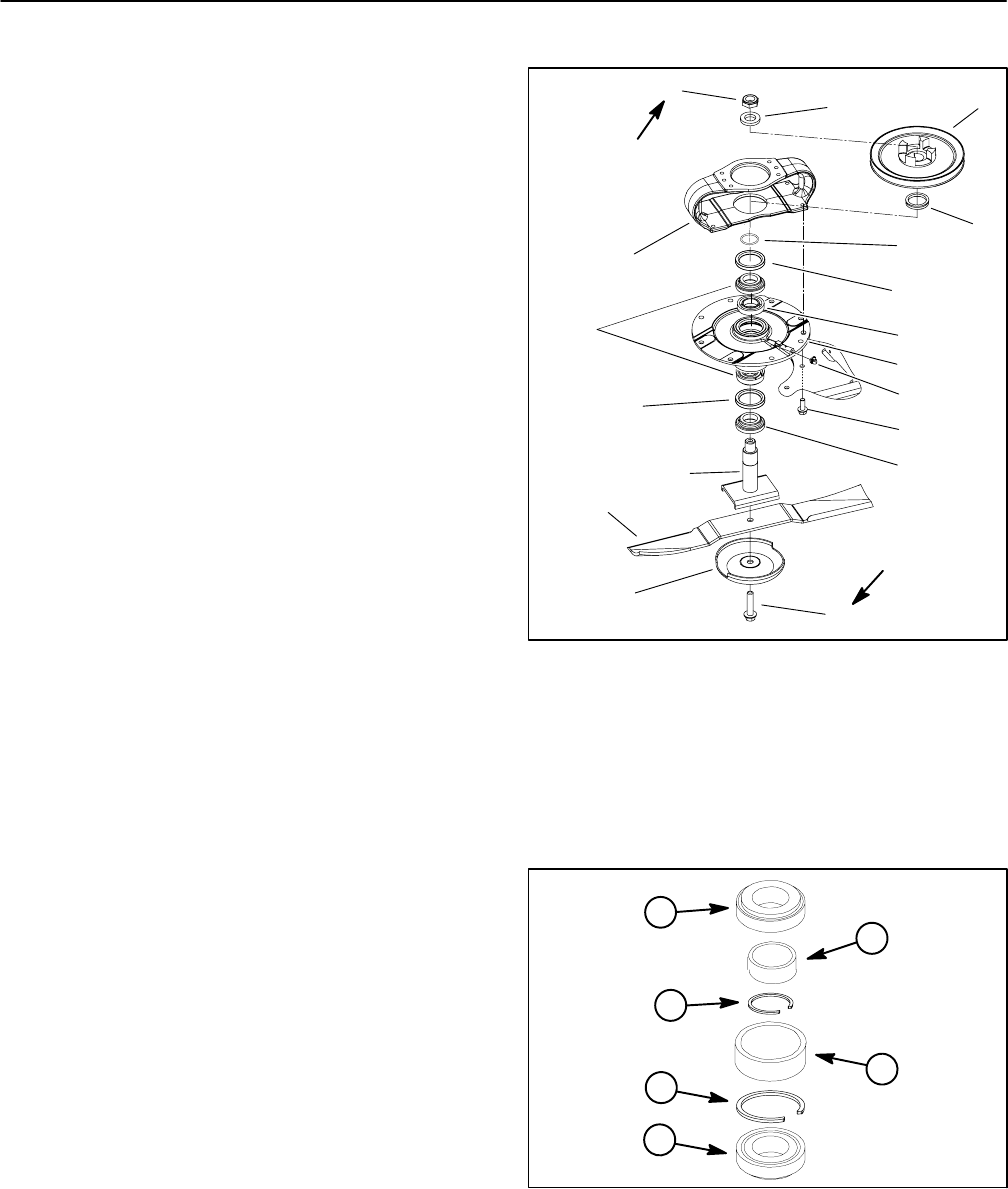
Blade Spindle Service
Disassembly
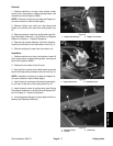
1. Park machine on a level surface, lower cutting units,
stop engine, engage parking brake, and remove key
from the ignition switch.
2. Remove belt covers from top of cutting deck. Loosen
idler pulley to release belt tension. Remove drive belt
from spindle to be serviced.
3. If drive spindle is to be serviced, remove hydraulic
motor from cutting deck (see Cutting Deck Motor Re-
moval in the Service and Repairs Section of Chapter 4
− Hydraulic Systems).
4. Start the engine and raise the cutting unit. Stop en-
gine and remove key from the ignition switch. Latch or
block up the cutting unit so it cannot fall accidentally.
Front deck can be tilted for spindle service (see Opera-
tor’s Manual).
5. Remove cutting blade, anti−scalp cup and bolt from
spindle to be serviced (see Operator’s Manual).
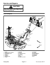
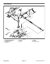
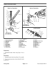
6. For drive spindle assemblies (Fig. 8), remove flange
head screws that secure spindle to deck. Remove
spindle housing assembly with motor mount from deck.
7. For driven spindle assemblies, remove flange head
screws and lock nuts that secure spindle to deck. Re-
move spindle housing assembly from the deck.
NOTE: Early production spindle assemblies included a
v−ring seal which has been found to be unnecessary.
Discard v−ring seal if found in spindle assembly.
8. Loosen and remove lock nut from top of spindle
shaft. Remove washer, pulley, and v−ring seal (if
equipped) from spindle. For drive spindle, remove motor
mount.
9. Remove the spindle shaft from the spindle housing
which may require the use of an arbor press. The spacer
should remain on the spindle shaft as the shaft is being
removed.
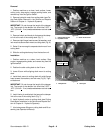
10.Remove seals from spindle housing.
11.Allow the bearings, inner spacer and spacer ring to
drop out of the spindle housing.
12.Using a punch and hammer, drive both of the bearing
cups out of the spindle housing. Remove the large outer
spacer from the housing.
13.The large snap ring can remain inside the spindle
housing. Removal of snap ring is very difficult.
1. Lock nut
2. Washer
3. Pulley (drive shown)
4. V−ring seal (if equipped)
5. Motor mount
6. O−ring (if equipped)
7. Oil seal
8. Bearing set
9. Spacer set (2 piece)
10. Spindle housing
11. Grease fitting
12. Flange head screw
13. Spacer
14. Spindle shaft
15. Blade
16. Anti−scalp cup
17. Blade bolt
Figure 8
130 to 150 ft−lb
(176 to 203 N−m)
9
14
11
1
15
16
3
4
5
6
8
7
10
12
7
13
2
85 to 110 ft−lb
(115 to 149 N−m)
17
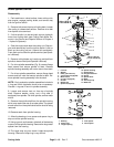
1. Bearing
2. Spacer ring
3. Large snap ring
4. Inner spacer
5. Outer spacer
Figure 9
4
1
1
2
3
5