


Groundsmaster 4000--DHydraulic System (Rev. B) Page 4 -- 64
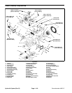
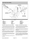
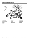
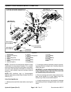
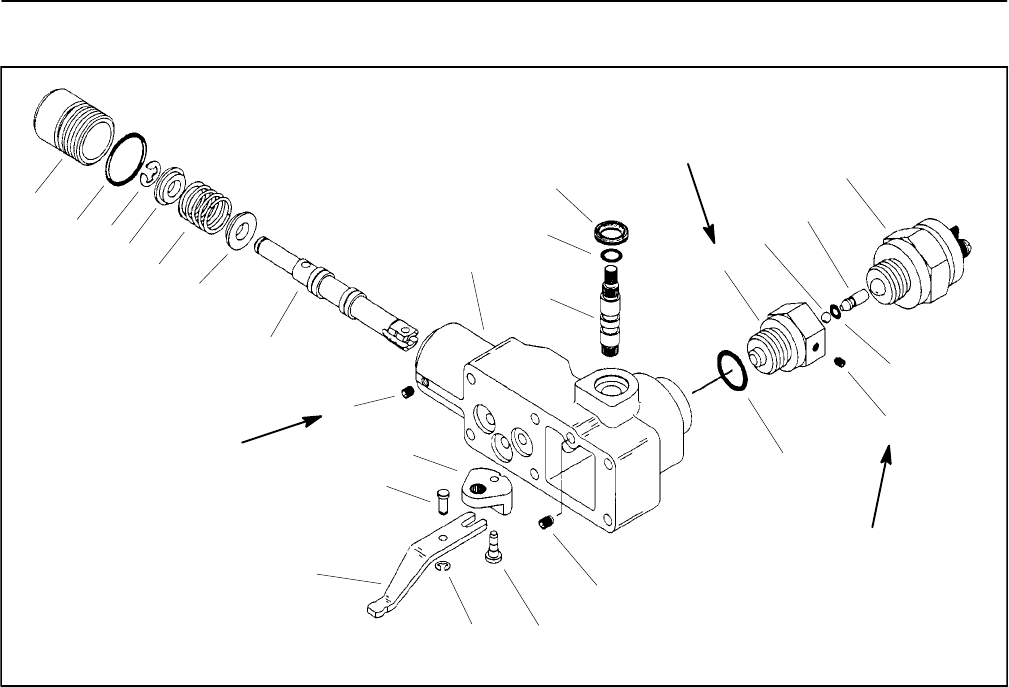
Piston Pump Control Assembly
1. Plug
2. O--ring
3. Retaining ring
4. Spring retainer
5. Spring
6. Spool valve
7. Control housing
8. Input shaft
9. O--ring
10. Wiper seal
11. O--ring
12. Adaptor
13. Ball
14. Pin
15. Neutral switch
16. O--ring
17. Set screw
18. Set screw
19. Pin
20. Retaining ring
21. Feedback link
22. Dowel pin
23. Bell crank
24. Set screw
Figure 47
12
16
11
17
15
14
9
7
4
6
24
22
21
20
19
18
5
10
8
13
23
4
3
2
1
28 to 34 in--lb
(3.2 to 3.8 N--m)
17 to 26 in--lb
(2 to 3 N--m)
44 to 52 ft--lb
(60to70N--m)
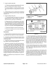
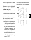
Disassembly -- Manual Servo Control Assembly
1. Remove wiper seal with screw driver. Remove set
screw (18) that retains input shaft and remove input
shaft from control housing. Remove o--ring from shaft.
2. Remove set screw (24) from plug that retains valve
spool. Remove plug from control housing and o--ring
from plug.
3. Removeretaining ring (20) from pinthat retains feed-
back link and spool valve. Remove pin, feedback link,
spool valve, and bell crank from control housing.
4. Compress spring and remove retaining ring (3). Re-
move spring retainer, spring, and secondspring retainer
from spool valve.
5. Clean all parts and lubricate in clean hydraulic oil for
reassembly.
Reassembly -- Manual Servo Control Assembly
1. Install spring retainer, spring, and second spring re-
tainer onto spool valve. Compress springto allow retain-
ing ring (3) to be installed onto spool valve.
2. Install spool valve into control housing making sure
that metering notches on spool valve can be seen in the
metering ports.
3. Position bell crank in housing. Slide feedback link
into position between clevis on valve spool, aligning
holes, and install dowel pin and retaining ring (20).
4. Install new o--ring (9) onto input shaft. Hold bellcrank
in position with feedback link slot and align splined hole
of bell crank with input shaftcavity. Install input shaft into
control housing and bell crank.