


Groundsmaster 4000--D Hydraulic System (Rev. B)Page 4 -- 33
Procedure for Cutting Deck Manifold Relief
Pressure Test
1. Make sure hydraulic oil is at normal operating tem-
perature by operating the machine for approximately 10
minutes. Make sure the hydraulic tank is full.
2. Park machine on alevel surface withthe cutting units
lowered and off. Make sure engine is off and the parking
brake is engaged.
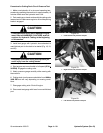
CAUTION
Prevent personal injury and/or damage to equip-
ment. Read all WARNINGS, CAUTIONS, and Pre-
cautions for Hydraulic Testing at the beginning
of this section.
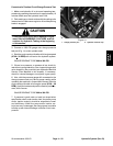
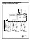
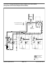
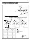
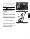
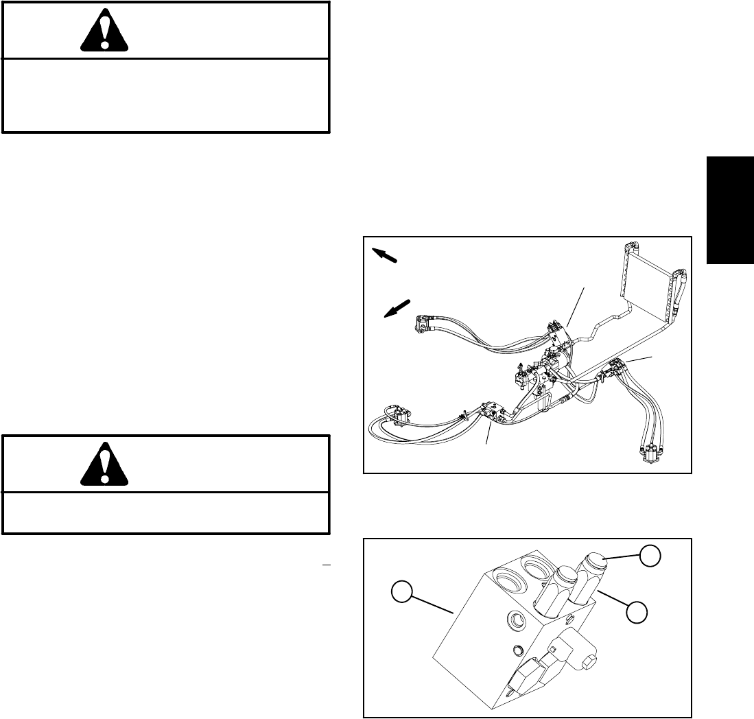
3. Locate deck manifold to be tested (Fig. 22). Discon-
nect hydraulic hose at deck manifold port (MP).
NOTE: An alternative to using manifold port (MP)
would be to disconnect the inlet hydraulic hose to the
deck motor.
4. Install tester in serieswith the the disconnected hose
and hydraulic manifold port (MP) (or motor inlet if hose
was disconnected at deck motor).
5. Make sure the flow control valve on the tester is fully
open.
6. Install tester in series with the hose and hydraulic fit-
ting. Make sure the flow control valve on tester is fully
open.
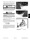
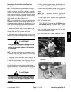
CAUTION
Keep away from decks during testto prevent per-
sonal injury from the cutting blades.
7. Start engine and move throttle to full speed (2730 +
30 RPM). Engage the cutting units.
8. Watch pressure gauge carefully while slowly closing
the flow control valve to fully closed.
9. As the relief valve lifts, system pressure should be
approximately:
3000 PSI for the front and left decks
2000 PSI for the right deck
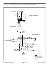
10.Disengage cutting units. Shut off engine. If specifica-
tion is not met, adjust or clean relief valve in deck man-
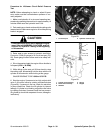
ifold port (R1BY). Adjust relief valve as follows:
NOTE: Do not remove valve from the hydraulic man-
ifold for adjustment.
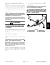
A. Remove cap on relief v alve with an allen wrench.
B. To increase pressure setting, turn the adjust-
ment screw on the valve in a clockwise direction. A
1/8 turnon the screwwill make a measurable change
in relief pressure.
C. To decrease pressure setting, turn the adjust-
ment screw on the valve in a counterclockwise direc-
tion. A 1/8 turn on the screw will make a measurable
change in relief pressure.
D. Reinstall and tighten cap to secure adjustment.
Recheck relief pressure and readjust as needed.
11.Disconnect tester from manifold and hose. Recon-
nect hydraulic hose that was disconnected for test pro-
cedure.
1. Front deck manifold
2. LH deck manifold
3. RH deck manifold
Figure 22
1
3
2
FRONT
RIGHT
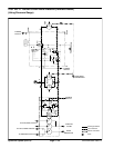
1. Deck manifold
2. Relief valve
3. Relief valve cap
Figure 23
1
3
2
Hydraulic
System