


Rev. E
Groundsmaster 4000−D Cutting UnitsPage 8 − 11
Assembly
IMPORTANT: If new bearings are installed into a
used spindle housing, it may not be necessary to re-
place the original large snap ring. If the original
snap ring is in good condition with no evidence of
damage (e.g. spun bearing), leave the snap ring in
the housing and discard the snap ring that comes
with the new bearings. If the large snap ring is found
to be damaged, replace the snap ring. Replacement
bearings are sold only with a matched spacer ring
and large snap ring (Fig. 9). These parts cannot be
purchased separately.
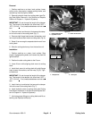
1. If large snap ring was removed, install snap ring into
spindle housing groove. Make sure snap ring is seated
in groove.
2. Install large outer spacer into top of spindle housing.
The spacer should fit against the snap ring.
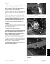
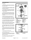
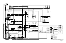
3. Using an arbor press, push the bearing cups into the
top and bottom of spindle housing. The top bearing cup
must contact the spacer previously installed, and the
bottom bearing cup must contact the snap ring. Make
sure that the assembly is correct by supporting the first
bearing cup and pressing the second against it (Fig 10).
4. Pack the bearing cones with grease. Apply a film of
grease on lips of oil seals and o−ring.
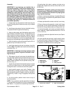
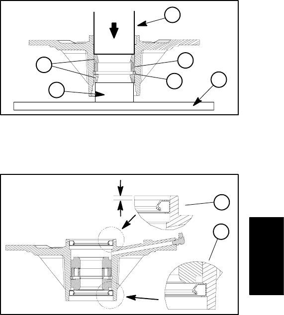
5. Install lower bearing and seal into bottom of spindle
housing. Note: The bottom seal must have the lip facing
out (down) (Fig. 11).
IMPORTANT: If bearings are being replaced, make
sure to use the spacer ring that is included in bear-
ing set (Fig. 9).
6. Slide spacer ring and inner spacer into spindle hous-
ing, then install upper bearing and seal into top of hous-
ing. Note: The upper seal must have the lip facing in
(down) and be recessed into the spindle housing .095”
(2.4 mm) (Fig. 11).
7. Inspect the spindle shaft and spindle spacer to make
sure they are free of burrs or nicks that could possibly
damage the seals. Lubricate the shaft with grease.
8. Install spindle spacer onto shaft. Carefully slide
spindle shaft up through spindle housing. The bottom
seal and spindle spacer fit together when the spindle is
installed fully. Install o−ring (if equipped) onto spindle
shaft.
9. For drive spindle, position motor mount to top of
spindle assembly.
NOTE: Early production spindle assemblies included a
v−ring seal which has been found to be unnecessary. Do
not install a v−ring seal when assembling the spindle.
10.Install pulley (hub down), washer, and lock nut to
spindle shaft. Tighten lock nut from 130 to 150 ft−lb (176
to 203 N−m).
IMPORTANT: Pneumatic grease guns can produce
air pockets when filling large cavities and therefore,
are not recommended to be used for proper greas-
ing of spindle housings.
11.Attach a hand pump grease gun to grease fitting and
fill housing cavity with grease until grease starts to come
out of lower seal.
12.Rotate spindle shaft to make sure that it turns freely.
13.Secure drive spindle assembly to deck with flange
head screws. Driven spindle assemblies are attached to
the deck with flange head screws and flange lock nuts.
14.Install cutting blade, anti−scalp cup and bolt (see Op-
erator’s Manual). Tighten blade bolt from 85 to 110 ft−lb
(115 to 149 N−m).
15.Install drive belt and adjust belt tension (see Opera-
tor’s Manual).
16.If drive spindle was removed, install hydraulic motor
to cutting deck (see Cutting Deck Motor Installation in
the Service and Repairs Section of Chapter 4 − Hydrau-
lic Systems). Install belt covers to cutting deck.
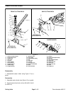
1. Bearing cups
2. Large snap ring
3. Large spacer
4. Arbor press
5. Support
6. Arbor press base
Figure 10
1
2
3
4
5
6
PRESS
1. Bottom seal installation 2. Upper seal installation
Figure 11
1
2
.095” (2.4 mm)
Cutting Units