


Groundsmaster 4000−DPage 5 − 16Electrical System
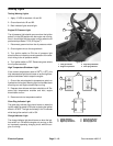
Hydraulic Valve Solenoids
There are four hydraulic valve solenoids on the Ground-
smaster 4000−D (Fig. 23). Testing of these solenoids
can be done with the solenoid on the hydraulic valve.
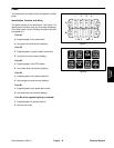
NOTE: Prior to taking small resistance readings with a
digital multimeter, short the meter test leads together.
The meter will display a small resistance value (usually
0.5 ohms or less). This resistance is due to the internal
resistance of the meter and test leads. Subtract this val-
ue from from the measured value of the component you
are testing.
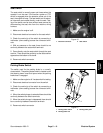
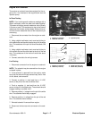
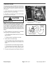
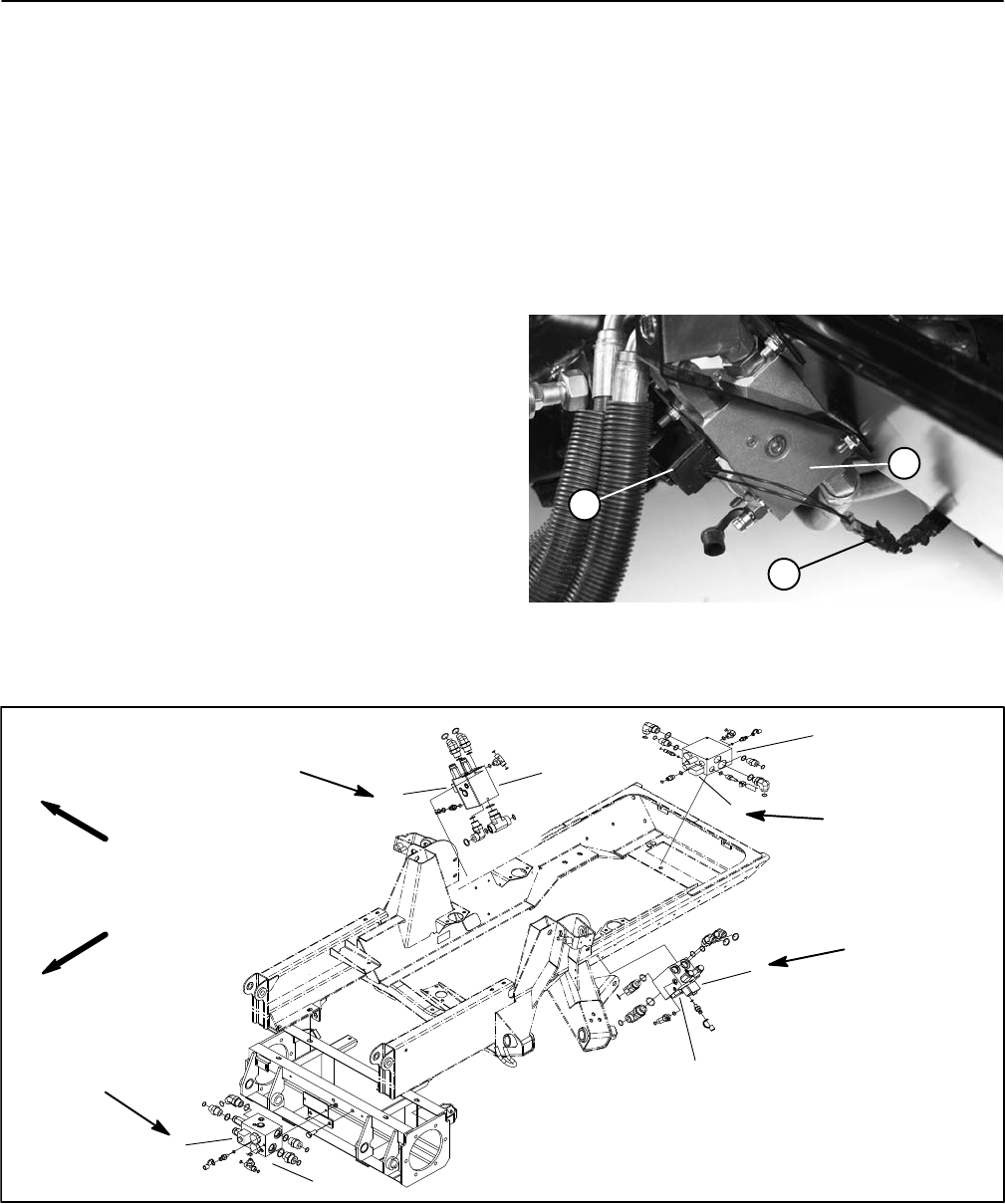
1. Make sure engine is off. Disconnect hydraulic valve
solenoid electrical connector (Fig. 22).
2. Apply 12VDC source directly to the solenoid. Listen
for solenoid to switch on.
3. Remove 12VDC source from the solenoid. Listen for
solenoid to switch off.
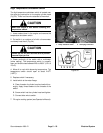
4. Measure resistance between the two connector ter-
minals. The resistance for the solenoid coil should be
about 7.2 ohms.
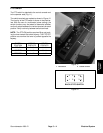
5. Install new solenoid if necessary.
A. Apply “Loctite 242” or equivalent to threads on
end of valve stem before installing nut.
B. Torque solenoid nut to specification identified in
Figure 23. Over−tightening may damage the sole-
noid or cause the valve to malfunction.
6. Reconnect electrical connector to the solenoid.
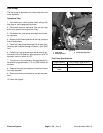
Figure 22
1. Manifold (RH shown)
2. Valve solenoid
3. Solenoid connector
2
1
3
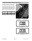
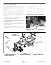
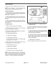
Figure 23
1. Hydraulic valve solenoid (decks)
2. Hydraulic manifold (decks)
3. Hydraulic valve solenoid (traction) 4. Hydraulic manifold (traction)
1
1
2
2
1
2
3
4
FRONT
RIGHT
4 to 6 ft−lb
(5 to 8 N−m)
2 to 5 ft−lb
(3 to 7 N−m)
2 to 5 ft−lb
(3 to 7 N−m)
2 to 5 ft−lb
(3 to 7 N−m)