


Groundsmaster 4000−D Page 5 − 15 Electrical System
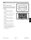
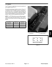
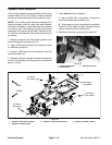
Start, Engine Shutdown, Seat, PTO, Alarm, and Over Temperature Relays
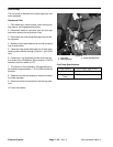
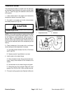
These six relays are located under the console housing
cover. The wiring harness is tagged to identify each
relay.
NOTE: The relays may be manufactured by one of two
different manufacturers. Verify manufacturer name and
part number before performing the resistance check on
the relay coil.
NOTE: Prior to taking small resistance readings with a
digital multi meter, short the meter test leads together.
The meter will display a small resistance value (usually
0.5 ohms or less). This resistance is due to the internal
resistance of the meter and test leads. Subtract this val-
ue from from the measured value of the component you
are testing.
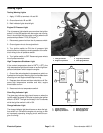
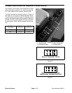
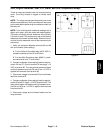
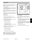
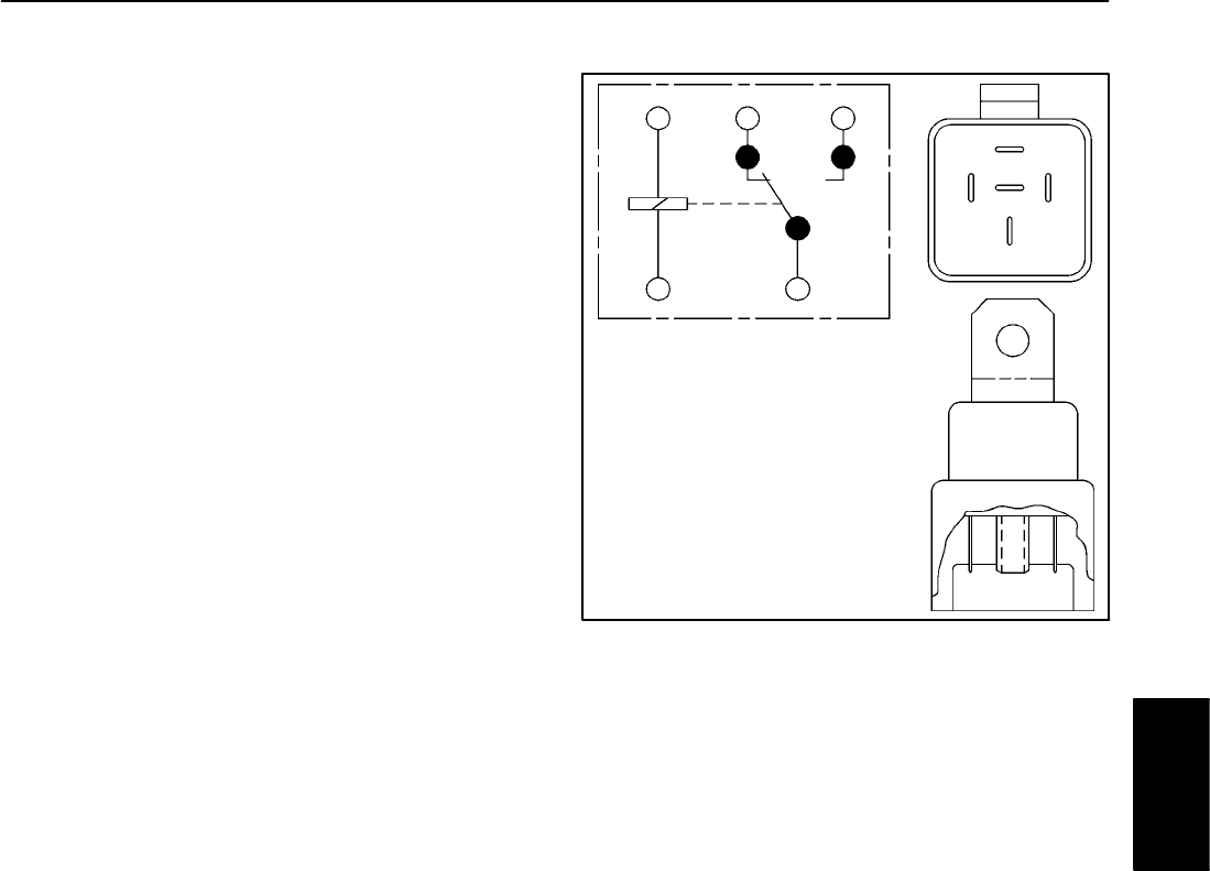
1. Verify coil resistance between terminals 85 and 86
with a multimeter (ohms setting):
A. For the Potter & Brumfield relay (#VF4−65F11),
resistance should be from 85 to 95 ohms.
B. For the Hella Electronics relay (#66211), resist-
ance should be from 70 to 80 ohms.
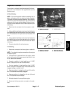
2. Connect multimeter (ohms setting) leads to relay ter-
minals 30 and 87. Ground terminal 86 and apply +12
VDC to terminal 85. The relay should make and break
continuity between terminals 30 and 87 as +12 VDC is
applied and removed from terminal 85.
3. Disconnect voltage from terminal 85 and multimeter
lead from terminal 87.
4. Connect multimeter (ohms setting) leads to relay ter-
minals 30 and 87A. Apply +12 VDC to terminal 85. The
relay should make and break continuity between termi-
nals 30 and 87A as +12 VDC is applied and removed
from terminal 85.
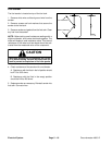
5. Disconnect voltage and multimeter leads from the
relay terminals.
Figure 21
86
85
87A 87
30
86
87A
30
87
85
Electrical
System