


Groundsmaster 4000--D Hydraulic System (Rev. B)Page 4 -- 15
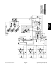
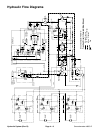
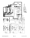
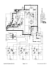
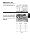
Mow
Hydraulic flow for the mow circuit is supplied by two sec-
tions of the gear pump. The gear pump section closest
to the piston (traction) pump supplies hydraulic flow to
the side c utting units, while the next gear pump section
supplies the front cutting unit.
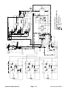
Each cutting deck is controlled by a hydraulic manifold
equipped with a solenoid control valve (SV1), bypass
cartridge (BY1), brake cartridge (BR1) and relief car-
tridge (R1BR). When the the deck solenoid valve (SV1)
is not energized (PTO switch OFF), hydraulic flow by--
passes the deck motor through the bypass cartridge
(BY1). When the PTO switch is turned ON, the solenoid
valve (SV1) energizes, causing a shift of the by--pass
cartridge (BY1) and allowing hydraulic flow to the deck
motor. Brake cartridge (BR1) and relief cartridge
(R1BR) control the stopping rate of the blade when the
solenoid control valve is de--energized as the PTO
switch is turned OFF.
Return oil from the deck motors is directed to the oil cool-
er and oil filter. Deck motor case drain leakage returns
to the hydraulic reservoir.
Maximum mow circuit pressure is limited at each deck
by a relief valve (R1BY) in the hydraulic manifold. The
front and left deck relief valves are set at 3000 PSI and
the right deck relief valve is set at 2000 PSI.
Circuit pressure can be measured at port (G) of the hy-
draulic manifold for each cutting deck.
Hydraulic
System