


Groundsmaster 4000--D Hydraulic System (Rev. B)Page 4 -- 75
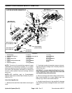
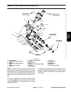
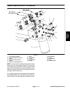
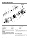
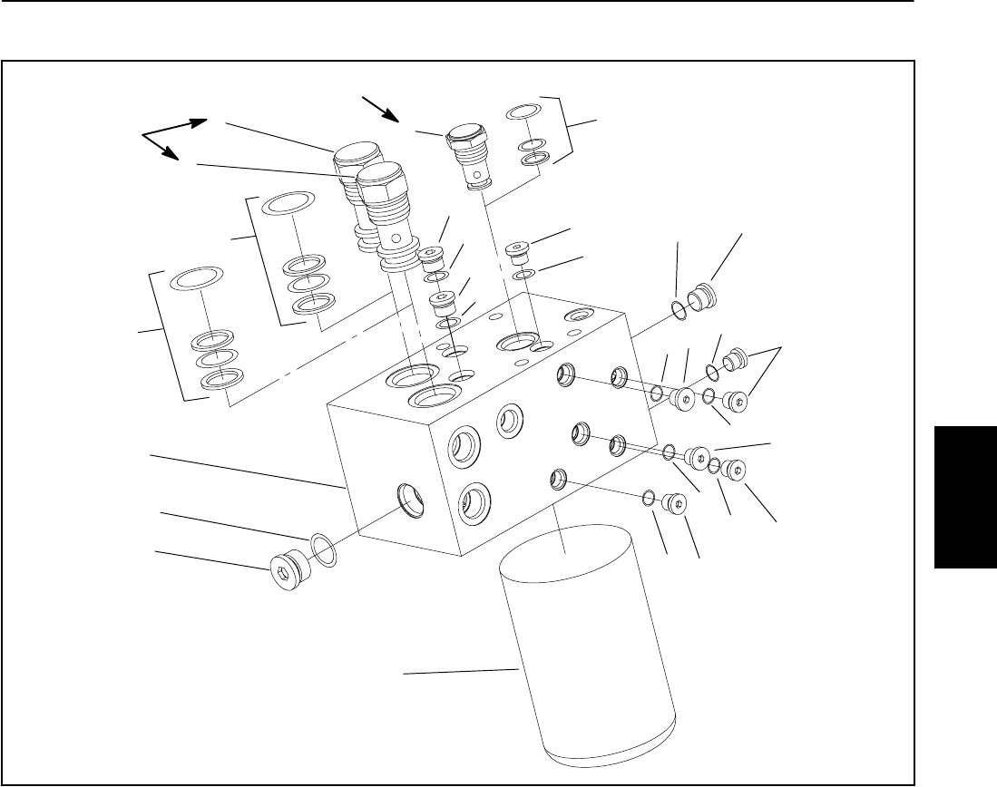
Hydraulic Manifold Service: Filter Manifold
1. Filter manifold assembly
2. Check valve (Reservoir return)
3. Seal kit
4. Check valve (Filter bypass)
5. Seal kit
6. Check valve (Charge pressure)
7. Seal kit
8. Plug (SAE #4)
9. O--ring
10. Plug (SAE #6)
11. O--ring
12. Plug (SAE #5)
13. O--ring
14. Plug (SAE #10)
15. O--ring
16. Oil filter element
Figure 57
4
2
6
10
12
8
10
8
12
5
3
7
9
15
1
13
11
16
11
14
13
8
9
9
13
12
9
10
11
60 to 70 ft--lb
(81to95N--m)
35 to 40 ft--lb
(47to54N--m)
NOTE: The ports on the manifold are marked for easy
identification of components. Example: P2 is the gear
pump connection port and CD is the connection for the
case drain from the deck motors (See Hydraulic Sche-
matics to identify the function of the hydraulic lines and
cartridge valves at each port).
For cartridge valve service procedures, see Hydraulic
Control Manifold Service: 4 Wheel Drive in this section.
Refer to Figure 57 for cartridge valve installation torque.
Hydraulic
System