


Groundsmaster 4000--D Hydraulic System (Rev. B)Page 4 -- 83
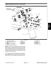
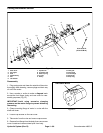
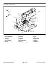
4. Remove motor from vise and remove rotating as-
sembly (4) from motor housing.
5. Remove the camplate insert (5) from housing. Use
caution not to mar the finish that makes contact with pis-
tons.
6. Remove retaining ring (6) from housing. Press shaft
from housing and remove shaft seal (8) and washer
(18).
7. Remove retaining rings (9) from shaft and remove
thrust races (10) and thrust bearing (13).
8. Discard the shaft seal and o--ring, and replace with
new items upon reassembly.
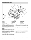
Inspection
1. Check the condition of the needle bearing (16) in
backplate (2) and replace if necessary.
2. Inspectvalve plate (12) on the bronze side next tothe
piston block for wear. A smooth surface is required. Do
not lap valve plate bronze surface. Replace valve
plate if any wear exists.
3. Inspect the piston block surface that makes contact
with valve plate. This surface should besmooth and free
of deep scratches. Do not lap piston block.
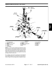
4. The pistons should move freely in the piston block
bore. If they are sticky in the bore, examine the bore for
scoring or contamination.
5. Examine the O.D. of the pistons for finish condition.
They should not show wear or deep scratches. Inspect
the shoes for a snug fit on the ball end of the pistons and
a flatsmooth surface that comes in contactwith the cam-
plate. Do not lap piston shoes.
6. Examine the spider for wear in the pivot area.
7. Examine the spider pivot to insure smoothness and
no signs of wear.
8. The polished finish on the shoe surface of the cam-
plate insert (5) should show no signs of scoring.
9. Inspect the shaft for wear in the seal, bearing and
spline areas.
10.Inspect thrust bearing (13) and races (10) for w ear.
11.Check the condition of the needle bearing (17) in
housing and replace if necessary.
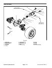
Reassembly
1. Clean all parts in suitable solvent and lubricate all in-
ternal parts with clean hydraulic oil before reassembly.
2. If necessary, install new needle bearing (17) inhous-
ing (3) with numbered end of the bearing outward.
3. Install retaining ring (9) on shaft. Install thrust race
(10), thrust bearing (13), and second thrust race (10).
Secure with second retaining ring (9).
4. Install shaft in housing. Install washer (18), newshaft
seal (8), and retaining ring (6).
5. Install camplate insert (5) with the lettering side of in-
sert to the front of the housing. Use petroleum jelly to
hold in place during assembly.
6. Install rotating assembly (4) into housing. Make sure
that piston shoesmake contact with the camplate insert.
7. Clamp motor assembly in a protected jaw vise with
the open end of the housing up.
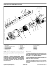
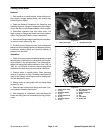
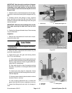
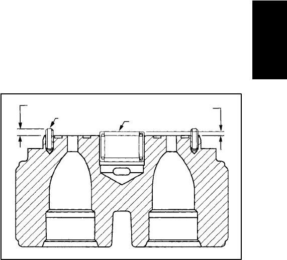
8. If roll pins were removed, install to dimension shown
in Figure 63 and with opening of roll pin oriented away
from bearing within 5 degrees of bearing center line.
9. To replace bearing (16) in backplate (2). Press bear-
ing down to the dimension shown (Fig. 63) protruding
from backplate with numbered end of bearing facing up
next to valve plate.
Roll Pin (15)
Bearing
.173 in (4.39 mm)
.090 in (2.3 mm)
Figure 63
10.Apply small amount of petroleum jelly to the steel
side of valve plate (12) to hold in place for installation.
Place the valve plate in position onto the backplate (2),
with steel side against backplate, bronze colored side
against piston block.
11.Placing new o--ring (11) onto backplate, install back-
plate assembly (2) onto housing assembly. Make sure
valve plate stays in position.
12.Insert cap screws and torque from 15 to 18 ft--Ib (20
to 24 N--m) in a criss--cross pattern.
13.Fill case half full of new hydraulic oil.
Hydraulic
System