


Groundsmaster 4000--D Hydraulic System (Rev. B)Page 4 -- 85
Cutting Deck Motor
Removal
1. Park machine on a level surface, lower cutting units,
stop engine, engage parking brake, and remove key
from the ignition switch.
2. Read the General Precautions for Removing and
Installing Hydraulic System Components at the begin-
ning of the Service and Repairs section of this chapter.
3. Disconnect hydraulic lines from deck motor. Put
caps or plugs on fittings and hoses to prevent contami-
nation. Tag hydraulic lines for proper reassembly.
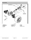
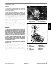
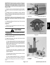
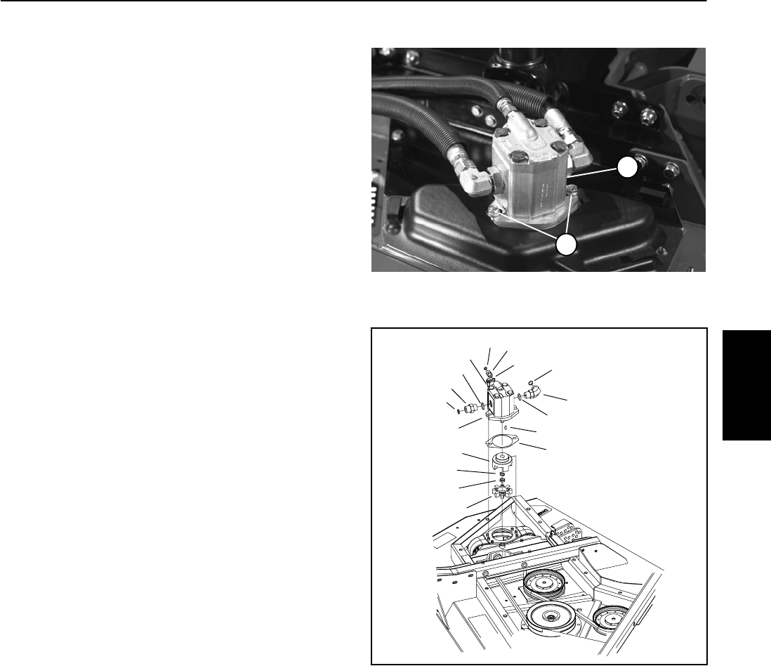
4. Removetwo flange head screws that secure hydrau-
lic motor to motor mount (Fig. 64).
5. Carefully remove hydraulic motor from cutting deck
taking care not to damage spider hub attached to motor.
Locate and remove spider and mounting shim(s) (if
present) from the deck.
Installation
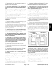
1. Check for proper clearance between spider hub and
spindle pulley. Install motor to cutting deck without plac-
ing the spider in the spindle pulley. The clearance be-
tween hub and pulley valleys should be from .830” to
.930” (21.1 to 23.6 mm). If required,use mounting shims
between motor and motor mount to adjust clearance.
2. Position spider in spindle pulley. Place mounting
shim(s) (if required) on deck. Carefully install hydraulic
motor to the cutting unit taking care not to damage spi-
der hub attached to motor.
3. Secure motor to cutting deck with two flange head
screws (Fig. 64).
4. Remove caps or plugs from fittings and hoses. Con-
nect hydraulic hoses to deck motor.
5. After assembly is completed, verify that hydraulic
hoses and fittings are not contacted by moving compo-
nents.
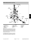
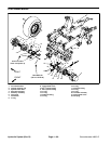
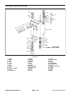
1. Cutting deck motor 2. Flange head screw
Figure 64
2
1
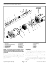
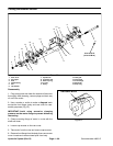
1. Cutting deck motor
2. O--ring
3. Hydraulic adapter
4. O--ring
5. Flange head screw
6. O--ring
7. Hydraulic adapter
8. O--ring
9. 90
o
hydraulic fitting
10. Woodruff key
11. Shim (if required)
12. Spider
13. Nut
14. Tab washer
15. Spider hub
Figure 65
9
12
15
11
2
1
5
7
6
8
3
4
2
4
10
13
14
Hydraulic
System