


Groundsmaster 4000−D Page 3 − 17 Kubota Diesel Engine (Rev. B)
Coupling Disassembly
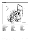
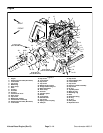
1. Remove adapter plate, spring coupling, and cou-
pling spacer from engine using Figure 9 as a guide.
Coupling Assembly
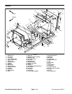
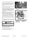
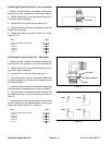
1. Position coupling spacer to engine and align mount-
ing holes. Use two shoulder bolts and lockwashers in the
positions shown in Figure 15 to secure the spacer to the
half threaded holes in engine flywheel. Torque shoulder
bolts from 10 to 12 ft−lb (13.6 to 16.3 N−m).
2. Install four cap screws and lockwashers to coupling
spacer and flywheel. Torque cap screws from 17 to 21
ft−lb (23 to 28.5 N−m).
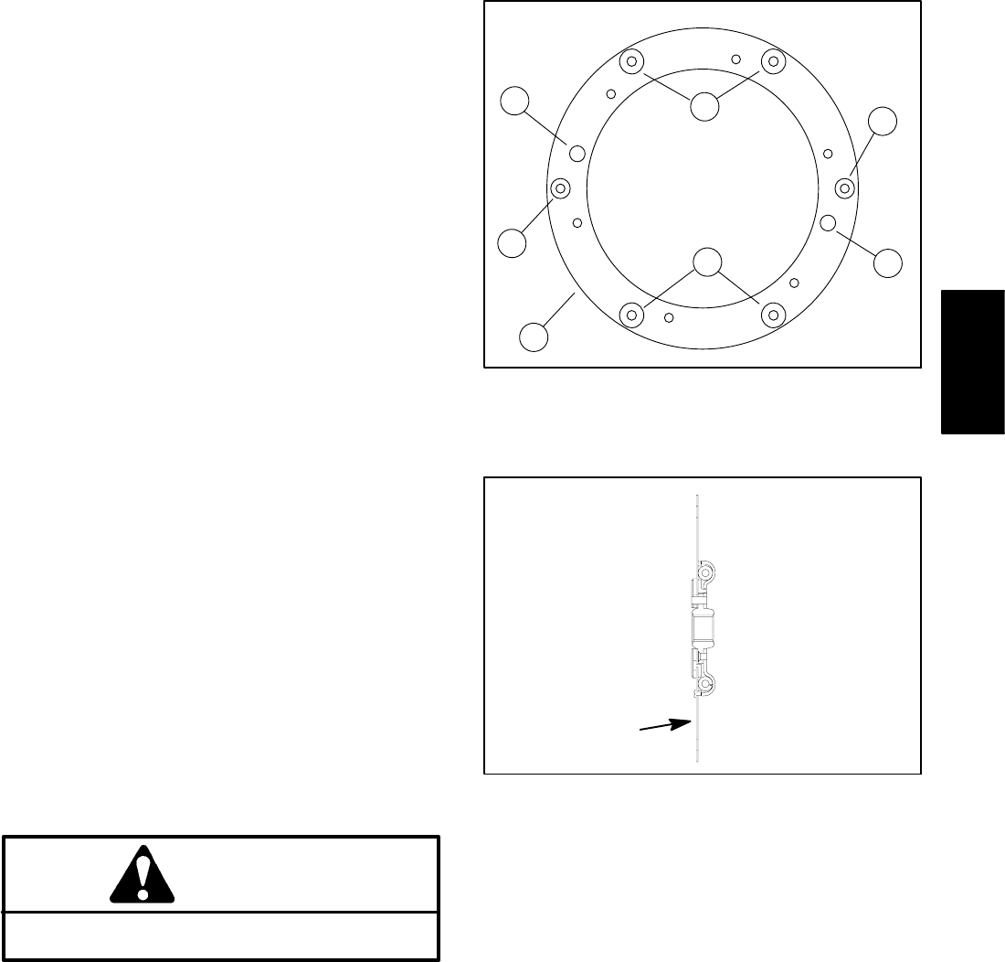
3. Place dowels in locating holes of coupling spacer
(Fig. 15).
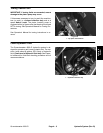
4. Position spring center coupling (coil springs toward
engine (Fig. 16)) over dowels. Secure coupling to cou-
pling spacer with cap screws and lockwashers. Torque
cap screws from 35 to 43 ft−lb (47.5 to 58.3 N−m).
5. Install plate pins into engine casting. Position pump
adaptor plate to engine using plate pins as alignment
points. Secure adaptor plate with cap screws and lock
washers using a star pattern tightening procedure.
Engine Installation
1. If removed, install engine mount brackets to the en-
gine using Figure 9 as a guide.
2. Connect hoist or lift to the front and rear lift tabs on
engine.
3. Position fan shroud around the engine fan.
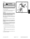
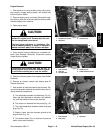
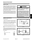
CAUTION
One person should operate lift or hoist while the
other person guides the engine into the machine
.
IMPORTANT: Make sure not to damage the engine,
fuel and hydraulic lines, electrical harness, or other
parts while installing the engine.
4. Slowly lower engine into the machine.
5. Align engine to the rubber engine mounts and secure
with cap screws, rebound washers, and flange head
locking nuts.
6. Secure fan shroud to the radiator with four cap
screws, flat washers, and locknuts. Make sure that
clearance between shroud and fan is at least .180” (4.6
mm) at all points.
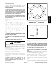
Figure 15
1. Coupling spacer
2. Shoulder bolt position
3. Cap screw position
4. Dowel position
2
3
1
2
4
3
4
Figure 16
Engine Side
Spring Center
Coupling
Hydraulic
Pump Side
7. Install coolant reservoir bracket and reservoir to fan
shroud.
8. Connect throttle cable to the speed control lever with
washer and lock nut. Install cable to mounting bracket
(Fig. 11). Adjust throttle cable (see Operator’s Manual).
9. Connect fuel line to the injection pump (Fig. 11).
10.Install traction cylinder assembly to engine adapter
plate.
IMPORTANT: Support hydraulic pump assembly to
prevent it from falling and being damaged.
11.Install hydraulic pump assembly to engine (see
Pump Assembly in Chapter 4 − Hydraulic Systems).
12.Connect two wires to neutral switch on traction
pump.
13.Connect wires and/or electrical connections to the
Kubota
Diesel Engine