


Groundsmaster 4000−D Page 6 − 15 Axles, Planetaries, and Brakes (Rev. B)
Bevel Gear Case and Axle Case
The following procedures assume the rear axle assem-
bly has been removed from the machine.
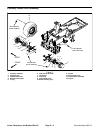
Removal
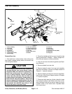
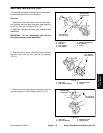
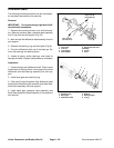
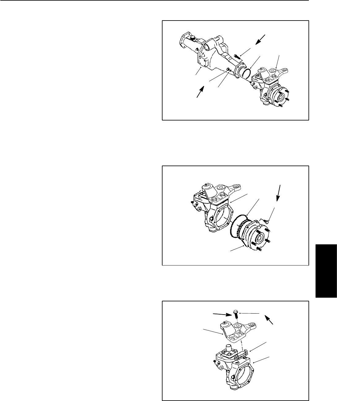
1. Remove the mounting screws, nuts, and lock wash-
ers. Remove the bevel gear case/axle case assembly
and O-ring from the axle support (Fig. 13).
2. Mark both right and left bevel gear case/axle case
assemblies.
IMPORTANT: Do not interchange right and left
bevel gear case/axle case assemblies.
1
2
3
4
5
6
1. Cap screw
2. Lock nut
3. Lock washer
4. Axle support
5. Bevel gear case/axle
case assembly
6. O-ring
Figure 13
35 to 41 ft−lb
(47 to 56 N−m)
35 to 41 ft−lb
(47 to 56 N−m)
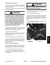
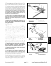
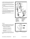
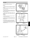
3. Remove the axle cover mounting screws. Remove
the axle cover from the axle case as an assembly
(Fig. 14).
1. Axle case
2. Axle cover assembly
3. Mounting screw
4. O-ring
Figure 14
1
2
3
4
17 to 20 ft−lb
(23 to 27 N−m)
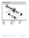
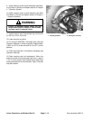
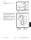
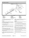
4. Remove the axle case support mounting screws, the
axle case support, and the support shims (Fig. 15).
1. Axle case
2. Axle case support
3. Mounting screw
4. Support shim
Figure 15
1
2
3
4
57 to 67 ft−lb
(77 to 91 N−m
)
Threadlocking
Compound
Axles, Planetaries,
and Brakes