


Rev. E
Groundsmaster 4000--D Hydraulic System (Rev. B)Page 4 -- 103
Disassembly
1. Removeoil from lift cylinder into a drain pan by slowly
pumping the cylinder shaft. Plug both ports and clean
the outside of the cylinder.
IMPORTANT: Prevent damage when clamping the
cylinder in a vise; clamp on the clevis only. Do not
close vise enough to distort the barrel.
2. Mount lift cylinder securely in a vise by clamping on
the clevis end of the barrel. Use of a vise with soft jaws
is recommended.
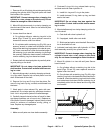
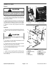
3. Loosen head from barrel:
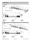
A. On cylinders without a r etaining ring slot in the
barrel (Figs. 78 and 79), use a spanner wrench to
loosen and remove collar from barrel.
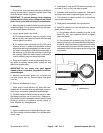
B. On cylinders with a retaining ring (Fig. 80), use a
spanner wrench to rotate head clockwise until the
edge of the retaining ring appears in the barrel open-
ing. Insert a screwdriver under the beveled edge of
the retaining ring to start the retaining ring through
the opening. Rotate the head counter--clockwise to
remove retaining ring from barrel and head.
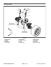
4. Extract shaft with head and piston by carefully twist-
ing and pulling on the shaft.
IMPORTANT: Do not clamp vise jaws against the
shaft surface. Protect shaft surface before mount-
ing in a vise.
5. Mountshaft s ecurely ina vise by clamping on the c le-
vis of the shaft. Remove lock nut and piston from the
shaft. Slide head off the shaft.
6. Remove Uni--ring and O--ring from the piston. Re-
move O--ring, back--up ring, rods eal, and dust seal from
the head.
7. Wash parts in clean solvent. Dry parts with com-
pressed air. D o not wipe parts dry with paper towels or
cloth. Lint in a hydraulic system will cause damage.
8. Carefully inspect internal surface of barrel for dam-
age (deep scratches, out--of--round, etc.). Replace en-
tire cylinder if barrel is damaged. Inspect piston rod and
piston for evidence of excessive scoring, pitting, or
wear. Replace any damaged parts.
Assembly
1. Make sure all parts are clean before assembly.
2. Coat new O--rings, Uni--ring, rod seal, back--up ring,
and dust seal with clean hydraulic oil.
A. Install Uni--ring and O--ring to the piston.
B. Install dust seal, O--ring, back--up ring, and dust
seal to the head.
IMPORTANT: Do not clamp vise jaws against the
shaft surface. Protect shaft surface before mount-
ing in a vise.
3. Mountshaft s ecurely ina vise by clamping on the c le-
vis of the shaft.
A. Coat shaft with clean hydraulic oil.
B. If equipped, install collar onto shaft.
C. Slide head and piston onto the shaft. Secure pis-
ton to shaft with lock nut.
4. Lubricate head and piston with hydraulic oil. Slide
shaft assembly carefully into cylinder barrel.
IMPORTANT: Prevent damage when clamping the
cylinder’s barrel into a vise; clamp on the clevis
only. Do not close vise e nough to distort the barrel.
5. Mount lift cylinder in a v ise with soft jaws. Secure
head in barrel:
A. On cylinders without a r etaining ring slot in the
barrel (Figs. 78 and 79), use a spanner wrench to
tighten collar into barrel.
B. On cylinders with a r etaining ring (Fig. 80), align
retaining ring hole in the head with the access slot in
the barrel. Insert the retaining ring hook into the hole
and rotate head clockwise until the retaining ring is
completely pulled into the barrel and the ring ends
are covered.
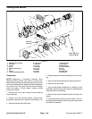
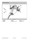
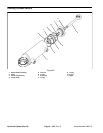
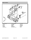
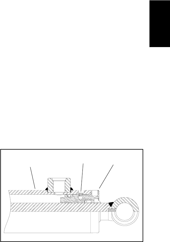
1. Barrel
2. Head
3. Retaining ring
Figure 80
1
3
2
Hydraulic
System