


Groundsmaster 4000−D Page 5 − 19 Electrical System
Fuel Gauge
The fuel gauge can be tested using a new gauge as a
substitute or with the use of a DC voltage source and a
variable resistance box.
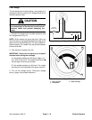
CAUTION
Make sure the voltage source is turned OFF be-
fore connecting it to the electrical circuit to avoid
electrical shock and prevent damaging the
gauge.
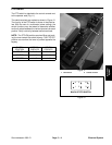
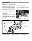
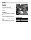
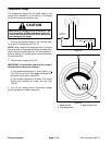
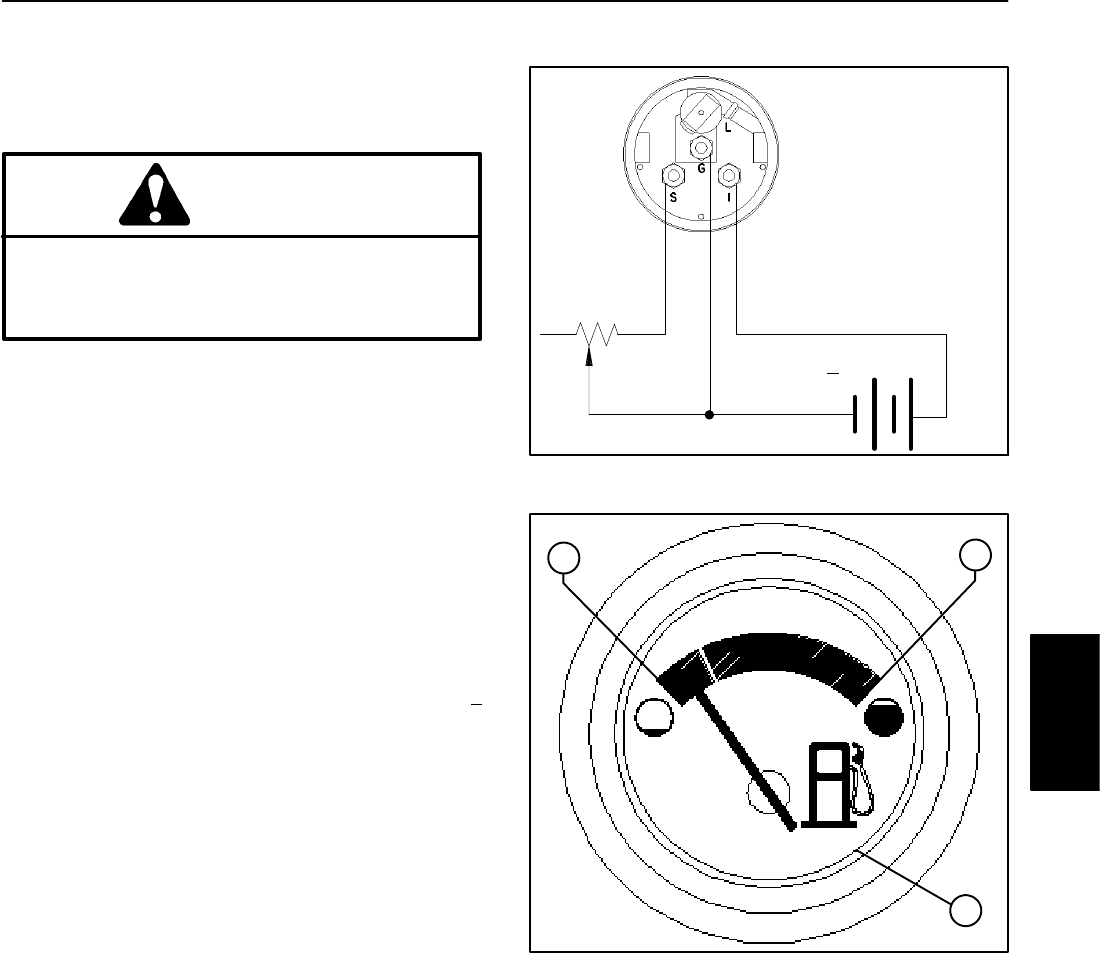
1. Connect fuel gauge to the variable resistance and
DC voltage source (Fig. 27).
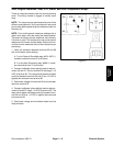
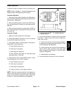
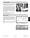
NOTE: When reading the gauge test point, there are
two white dots on the gauge face below the edge of the
glass cover for the each test point. For each variable re-
sistance setting, the needle must be pointed between
the two white dots.
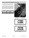
2. Take test point readings (Fig. 28).
IMPORTANT: Allow circuit to warm up for at least 5
minutes before taking test readings.
A. Set variable resistance to 240 ohms. Apply a 14 +
0.01 VDC to the circuit. The needle should point to
the left edge of the red area (empty).
B. Set variable resistance to 33 ohms. The needle
should point to the right edge of the green area (full).
3. Turn off the voltage source. Disconnect voltage
source, gauge, and variable resistance.
Figure 27
+
−
VARIABLE
RESISTANCE
14 VDC + 0.01 VDC
1. Empty position
2. Full position
3. Glass face edge
Figure 28
1
2
3
Electrical
System