


Groundsmaster 4000--DHydraulic System (Rev. B) Page 4 -- 86
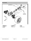
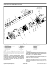
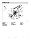
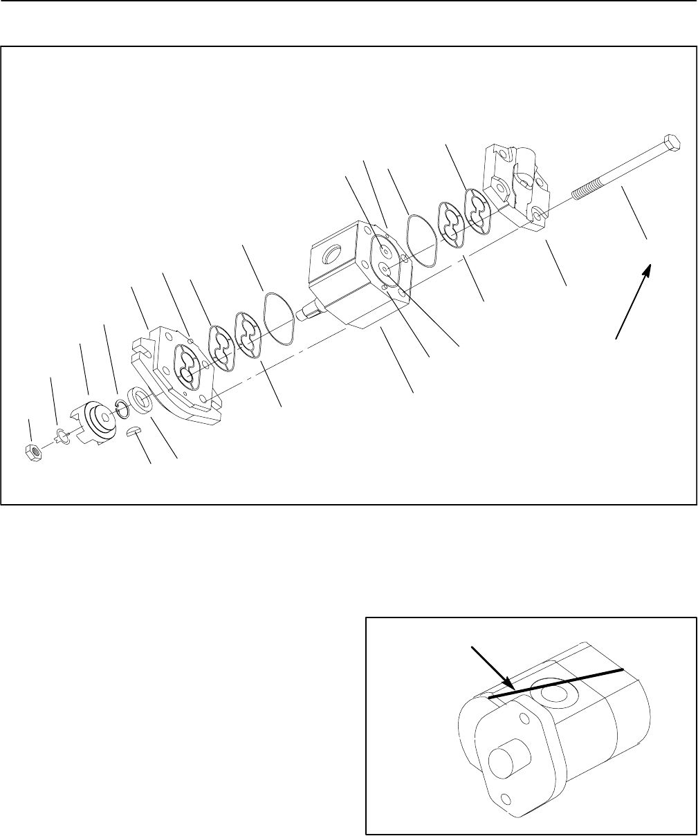
Cutting Deck Motor Service
1. Rear cover
2. Drive gear
3. Seal
4. Woodruff key
5. Nut
6. Tab washer
7. Spider hub
8. Pressure seal
9. Back--up ring
10. O--ring
11. Body
12. Idler gear
13. Cap screw
14. Front flange
15. Dowel pin
16. Snap ring
Figure 66
8
7
4
3
1
2
5
6
9
10
11
10
9
12
(45to55N--m)
33 to 40 ft--lb
13
8
14
15
15
15
16
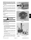
Disassembly
1. Plug motor ports and clean the outside of the motor
thoroughly. After cleaning, remove plugs and drain any
oil out of the motor.
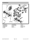
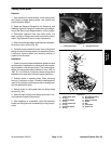
2. Use a marker or scribe to make a diagonal mark
across the front flange, body, and rear cover for reas-
sembly purposes (Fig. 67).
IMPORTANT: Avoid using excessive clamping
pressure on the motor flange to prevent distorting
the casting.
3. Clamp mounting flange of motor in a vise with the
shaft end down.
4. Loosen cap screws on the rear cover.
5. Take motor from the vise and remove cap screws.
6. Removefront flangefrom the body, then remove rear
cover. Locate and remove dowel pins from body.
Figure 67
DIAGONAL MARK