


Groundsmaster 4000--D Hydraulic System (Rev. B)Page 4 -- 87
IMPORTANT: Mark the relative positions of the gear
teeth and the bearing blocks so they can be re-
assembled in the same position. Do not touch the
gear surfaces as residue on hands may be corrosive
to gear finish.
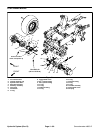
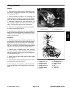
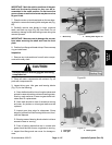
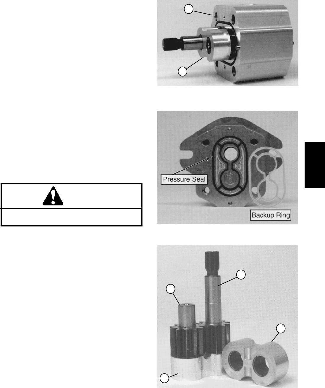
7. Placethe motor on its side and push on the rear bear-
ing block to remove the bearing block and gear set (Fig.
68).
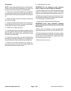
8. Carefully remove and discard o--rings, pressure
seals, and back--up rings (Fig. 69) from motor. Do not
cause any damage to the machined grooves during the
removal process.
IMPORTANT: Make sure not to damage the counter
bore when removing the shaft seal from the front
plate.
9. Position front flange with seal side up. Remove snap
ring and shaft seal.
Inspection
1. Remove any nicks and burrs from all motor compo-
nents with emery cloth.
CAUTION
Use eye protection such as goggles when using
compressed air.
2. Clean all motor components with solvent. Dry all
parts with compressed air.
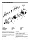
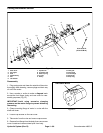
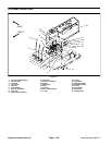
3. Inspect drive gear, idler gear and bearing blocks
(Fig. 70) for the following:
A. Gear shafts should be free of rough surfaces and
excessive wear at bushing points and sealing areas.
Scoring, rough surfaces, or wear on gear shafts indi-
cates need for replacement.
B. Gear teeth should be free of excessive scoring
and wear. Any broken or nicked gear teeth must be
replaced.
C. Inspect gear face edge for sharpness. Sharp
edges of gears will mill into bearing blocks and, thus,
must be replaced.
D. Bearing areas of bearing blocks should not have
excessive wear or scoring.
E. Face of bearing blocks that are in contact with
gears should be free of wear, roughness or scoring.
4. Inspect front flange and rear cover for damage or
wear.
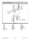
1. Motor body 2. Bearing block & gear set
Figure 68
2
1
Figure 69
1. Drive gear
2. Idler gear
3. Bearing block
Figure 70
1
3
3
2
Hydraulic
System