


Groundsmaster 4000−D Page 5 − 25 Electrical System
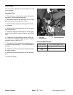
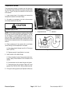
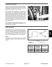
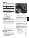
Traction Neutral Switch
The traction neutral switch is closed when the traction
pedal is in the neutral position and opens when the pedal
is depressed in either direction. The switch is located on
the right side of the piston (traction) pump.
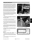
Test the switch by disconnecting the wires from the
switch terminals and connecting a continuity tester
across the two switch terminals. With the engine turned
off, slowly push the traction pedal in a forward or reverse
direction while watching the continuity tester. There
should be indications that the traction neutral switch is
opening and closing. Allow the traction pedal to return
to the neutral position. There should be continuity
across the switch terminals when the traction pedal is in
the neutral position.
See Piston Pump Control Assembly in Chapter 4 − Hy-
draulic Systems for disassembly and reassembly proce-
dures for the neutral switch.
1. Piston pump (bottom) 2. Neutral switch
Figure 37
1
2
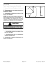
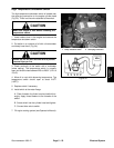
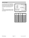
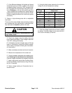
Diode Assemblies
The diodes D2, D4, D5, and D6 (Fig. 38) are used for cir-
cuit protection that occur when a hydraulic valve sole-
noid is de−energized. Diode D2 is in the Transport/Mow
circuit, D4 is in the left cutting deck circuit, D5 is in the
front cutting deck circuit, and D6 is in the right cutting
deck circuit. The diodes plug into the wiring harness.
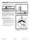
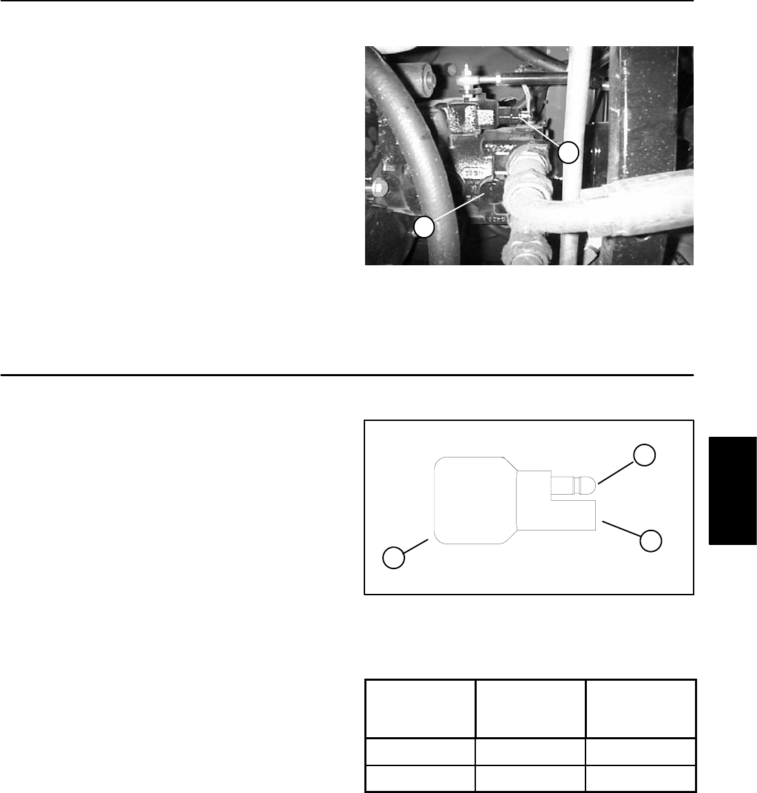
Testing
The diodes can be individually tested using a digital
multimeter (diode test or ohms setting) and the table to
the right.
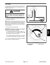
Figure 38
1
1. Diode
2. Male terminal
3. Female terminal
3
2
Multimeter
Red Lead (+)
on Terminal
Multimeter
Black Lead (−)
on Terminal
Continuity
Female Male YES
Male Female NO
Electrical
System