


Groundsmaster 4000--D Hydraulic System (Rev. B)Page 4 -- 39
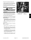
Procedure for Lift/Lower Circuit Relief Pressure
Test
NOTE: Before attempting to check or adjust lift pres-
sure, make sure that counterbalance pressure is cor-
rectly adjusted.
1. Make sure hydraulic oil is at normal operating tem-
perature by operating the machine for approximately 10
minutes. Make sure the hydraulic tank is full.
2. Park machine on alevel surface withthe cutting units
lowered and off. Make sure engine is off and the parking
brake is engaged.
CAUTION
Prevent personal injury and/or damage to equip-
ment. Read all WARNINGS, CAUTIONS, and Pre-
cautions for Hydraulic Testing at the beginning
of this section.
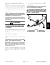
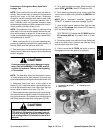
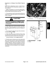
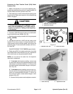
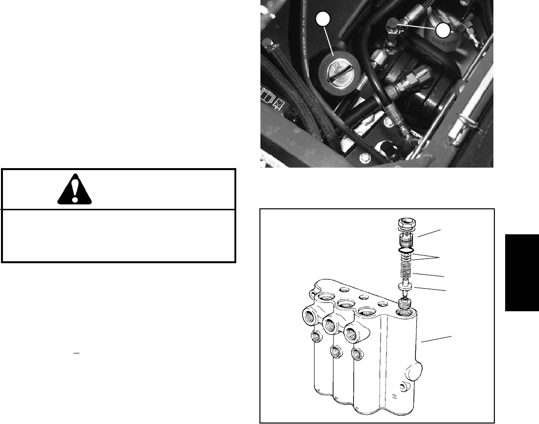
3. Raise seat to gain access to hydraulic test fitting.
Connect a 5,000 psi gauge to lift circuit test port (Fig.
28). Route gauge hose to allow seat to be safely low-
ered.
4. Sit on the seat and start the engine. Move throttle to
full speed (2730 +
30 RPM).
5. While sitting on the seat, pull lift lever back to raise
the cutting units. Momentarily hold the lever with the lift
cylinder at full extension while looking at the gauge.
GAUGEREADINGTOBE1525 to 1575 PSI.
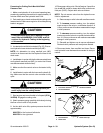
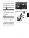
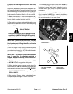
6. Stop the engine. If pressure is too high, adjust relief
valve in lift c ontrol v alve by rotating counterclockwise
(Figure 29). If pressure is too low, check for restriction
in pump intake line. Check the lift cylinder for internal
leakage. If cylinder is not leaking, adjust the relief valve
by rotating clockwise. If pressure is still too low, pump or
lift cylinder(s) should be suspected of wear, damage or
inefficiency.
1. Lift circuit port 2. Hydraulic reservoir cap
Figure 28
2
1
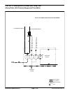
1. Control valve assembly
2. Relief valve assembly
3. Washers
4. Spring
5. Poppet
Figure 29
2
3
1
4
5
Hydraulic
System