


Groundsmaster 4000--D Hydraulic System (Rev. B)Page 4 -- 45
Procedure for Rear Traction Circuit (RV5) Relief
Pressure Test
1. Make sure hydraulic oil is at normal operating tem-
perature by operating the machine for approximately 10
minutes. Make sure the hydraulic tank is full.
2. Park machine on alevel surface withthe cutting units
lowered and off. Make sure engine is off and the parking
brake is engaged.
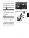
CAUTION
Prevent personal injury and/or damage to equip-
ment. Read all WARNINGS, CAUTIONS, and Pre-
cautions for Hydraulic Testing at the beginning
of this section.
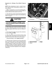
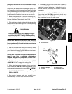
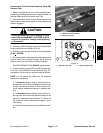
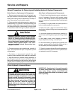
3. Connect a 1000 PSI gauge to test port on 2WD/4WD
control manifold under radiator (Fig. 33).
4. Start the engine and put throttle at full engine speed
(2730 +
30 RPM).
5. Operate the machine in 4WD with the cutting units
lowered. Drive down a slope in a forward direction, de-
crease pressure on the traction pedal, and monitor the
pressure gauge. Pressure should increase until the re-
lief valve lifts.
GAUGEREADINGTOBE750 PSI (approximate).
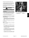
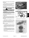
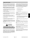
6. Relief valve (RV5) is located on the lower, front side
of the 2WD/4WD control manifold (Fig. 34). Adjustment
of the relief valve can be performed as follows:
NOTE: Do not remove the valve from the hydraulic
manifold for adjustment.
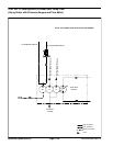
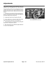
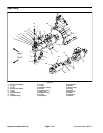
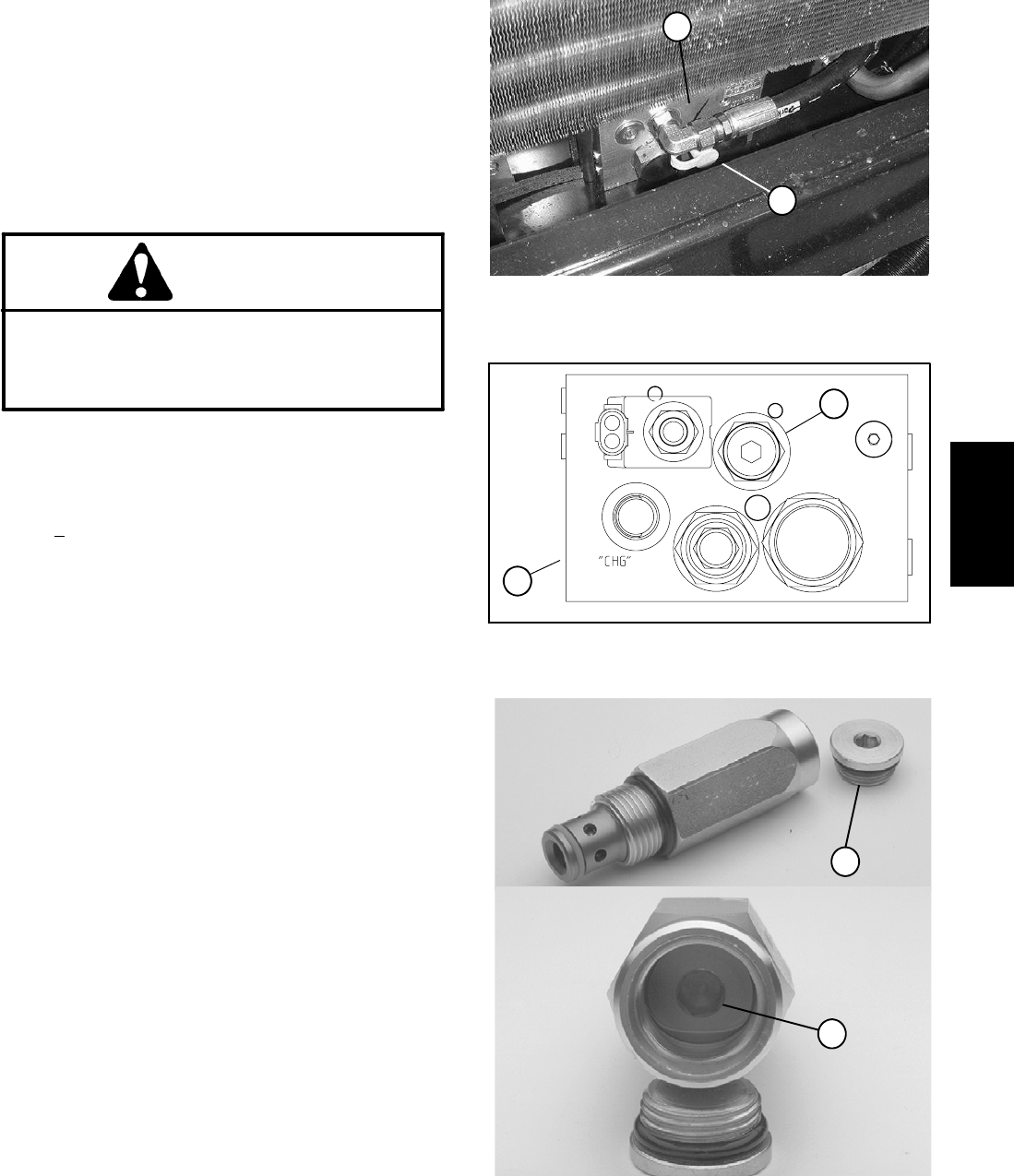
A. To increase relief pressure setting, remove cap
on relief valve and turn the adjustment socket on the
relief valve in a clockwise direction. A 1/8 turn on the
socket will make a measurable change in relief pres-
sure (Fig. 35).
B. To decrease pressure setting, remove cap on re-
lief valve and turn the adjustment socket on the relief
valve in a counterclockwise direction. A 1/8 turn on
the socket will make a measurable change in relief
pressure (Fig. 35).
C. Recheck relief pressure and readjust as needed.
1. 2WD/4WD control manifold
2. Relief valve test port
Figure 33
1
2
1. Manifold: lower side 2. Relief valve (RV5)
Figure 34
2
1
Figure 35
1. Relief valve cap 2. Adjustment socket
2
1
Hydraulic
System