Groundsmaster 4000--D Hydraulic System (Rev. B)Page 4 -- 13
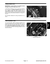
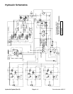
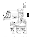
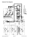
Raise Cutting Unit
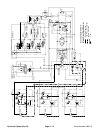
A three section gear pump is coupled to the piston (trac-
tion) pump. Thegear pump section farthest from the pis-
ton pump supplies hydraulic flow to the lift/lower control
valve and the steering control valve. Hydraulic flow from
this pump section is delivered to the two circuits through
a proportional flow divider. The gear pump takes its suc-
tion from the hydraulic reservoir.
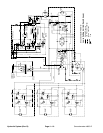
When the cutting units are in a stationary position, flow
from the gear pump is by--passed through the lift/lower
control valve, counterbalance manifold, oil filter, and
traction charge circuit.
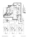
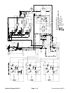
To raise a side cutting unit, the appropriate lift lever on
the lift/lower control valve is pulled to allow valve shift in
the lift/lower control. This valve change allows hydraulic
pressure to the piston end of the lift cylinder and causes
the shaft to extend, raising the cutting unit. Oil from the
rod end of the cylinder flows to the traction charge cir-
cuit. When the lift lever is released,the lift cylinder isheld
in position.
To raise the front cutting unit, the center lift lever on the
lift/lower control valve is pulled to allow valve shift in the
lift/lower control. This valve change allows hydraulic
pressure to the rod end of the front deck lift cylinders,
causing the cylinders to retract. As the cylinders retract,
the front deck raises. Oil from the piston end of the cylin-
der returns to the hydraulic reservoir. When the lift lever
is released, the lift cylinder is held in position.
An adjustable counterbalance valve maintains back
pressure on the lift cylinders. A relief valve located in the
lift/lower control valve limits c ircuit press u re. Excess cir-
cuit flow is routed to the oil filter and then to the traction
charge circuit.
Hydraulic
System


