


Rev. F
Groundsmaster 4000--D Hydraulic System (Rev. B)Page 4 -- 71
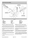
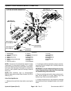
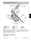
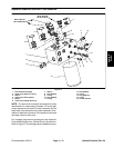
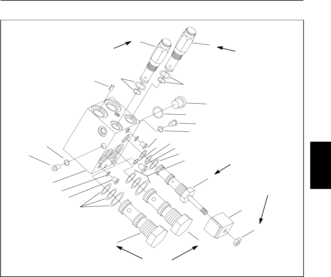
Hydraulic Control Manifold Service: Deck Drive
1. Manifold body
2. Spool logic cartridge (port BY1)
3. Seal kit
4. Spool logic cartridge (port BR1)
5. Seal kit
6. Relief valve (port R1BY)
7. Seal kit
8. Solenoid valve (port SV1)
9. Seal kit
10. Solenoid coil
11. Nut
12. Relief pilot cartridge (port R1BR)
13. Seal kit
14. Plug (SAE #2)
15. O--ring
16. Plug (SAE #4)
17. O--ring
18. Plug (SAE #8)
19. O--ring
20. Orifice plug (port MR)
Figure 53
10
8
9
9
2
16
17
4
14
15
12
13
20
6
7
18
19
14
15
1
5
3
14
15
9
11
80 ft--lb
(108 N--m)
12 to 15 ft--lb
(16to20N--m)
30 to 35 ft--lb
(41to47N--m)
30 to 35 ft--lb
(41to47N--m)
2to5ft--lb
(3 to 7 N--m)
NOTE: The ports on the manifold are marked for easy
identification of components. Example: SV1 is the deck
solenoid valve andP1 isthe gear pump connectionport.
(See Hydraulic Schematics to identify the functionof the
hydraulic lines and cartridge valves at each port loca-
tion).
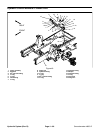
The control manifolds for the three cutting decks are
very similar. Note: When servicing the deck control
manifolds, DO NOT interchange parts from one control
manifold to another.
For solenoid and control valve service procedures, see
Hydraulic Control Manifold Service: 4 Wheel Drive in
this section. Refer to Figure 53 for cartridge valve instal-
lation torque.
Hydraulic
System