


Groundsmaster 4000−D Page 5 − 17 Electrical System
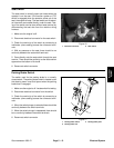
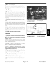
Engine Run Solenoid
The engine run solenoid must be energized for the en-
gine to run. It is mounted on the engine block near the
injection pump.
In Place Testing
NOTE: Prior to taking small resistance readings with a
digital multimeter, short the meter test leads together.
The meter will display a small resistance value (usually
0.5 ohms or less). This resistance is due to the internal
resistance of the meter and test leads. Subtract this val-
ue from from the measured value of the component you
are testing.
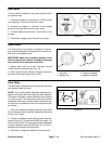
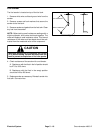
1. Disconnect the connector from the engine run sole-
noid.
2. Using a digital multimeter, touch one lead to the pin
of the black wire and the other lead to the pin of the white
wire. The resistance of the pull coil should be about 0.26
ohms.
3. Using a digital multimeter, touch one lead to the pin
of the black wire and the other lead to the pin of the red
wire. The resistance of the hold coil should be about
10.9 ohms.
4. Connect solenoid to the wiring harness.
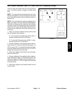
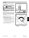
Live Testing
1. Disconnect connector from the engine run solenoid.
NOTE: The solenoid may be removed from the engine
or tested in place.
2. If the solenoid is removed from the engine, make
sure that the solenoid linkage moves freely and is free
of dirt, debris, and corrosion.
3. Connect a positive (+) test lead from a 12 VDC
source to the pins of the red and white wires.
4. Touch a negative (−) test lead from the 12 VDC
source to the pin of the black wire. The solenoid should
engage making an audible “click”.
5. Remove positive (+) voltage from the pin of the white
wire. The solenoid should stay engaged.
6. Remove positive (+) voltage from the pin of the red
wire. The solenoid should release.
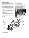
7. Reinstall solenoid if removed from engine.
8. Reconnect the harness wire connector to the sole-
noid.
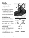
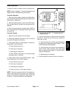
Figure 24
1. Engine run solenoid
2. Solenoid connector
3. Injection pump
2
3
1
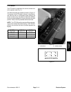
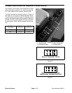
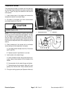
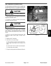
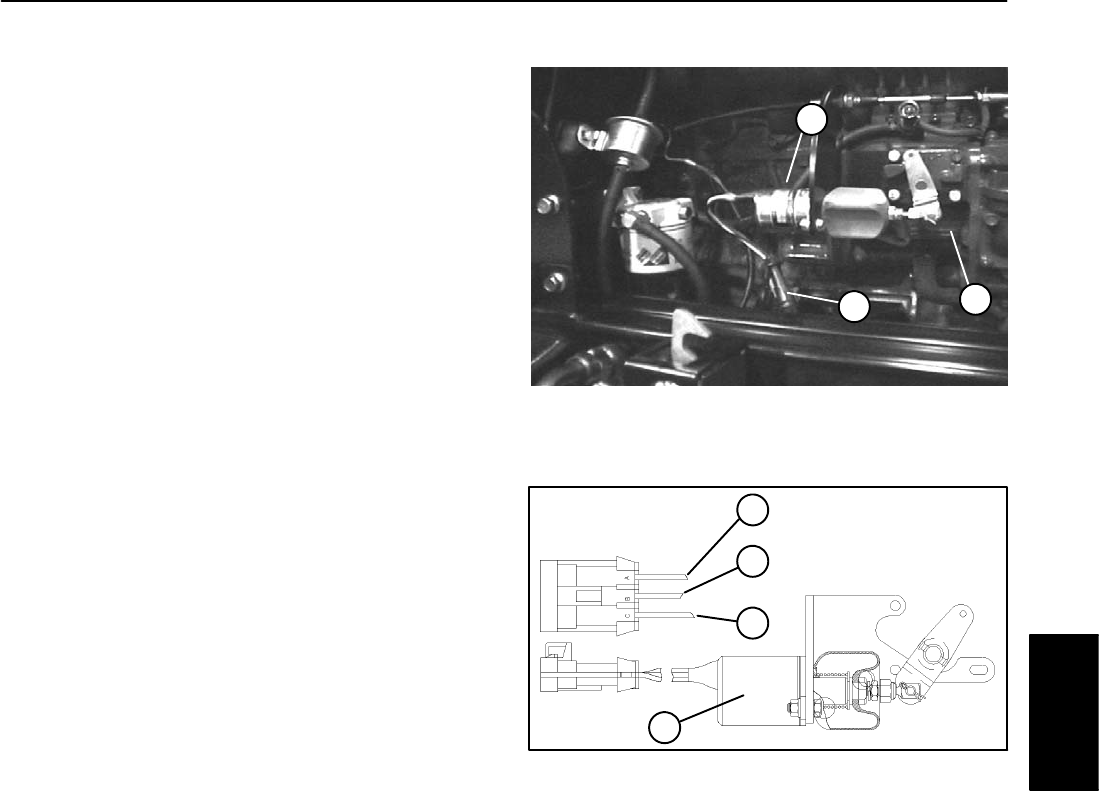
1. Engine run solenoid
2. Red wire (hold coil)
3. White wire (pull coil)
4. Black wire (common)
Figure 25
2
3
4
1
Electrical
System